Last Update: 2026-09-30
IEEE 802.11 MAC の基礎
IEEE 802.11 MAC architecture
IEEE Std 802.11-2020 - Figure 10-1—Non-DMG non-CMMG non-S1G STA MAC architecture (p.1630) に、Wi-Fi 通信における MAC アーキテクチャの図が書かれてる。下の図は、 Figure 10-1 を元に作成した図。
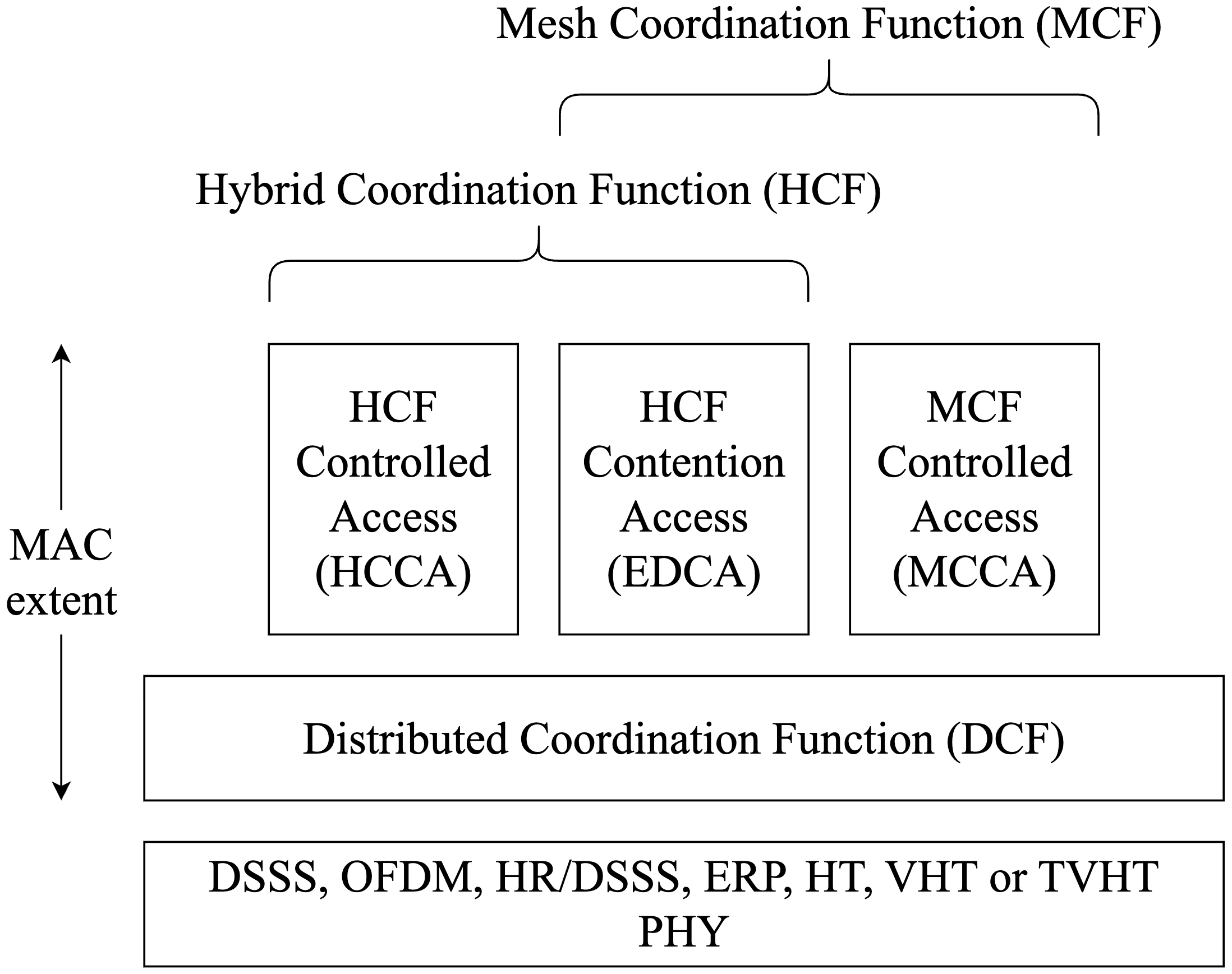
また、MAC 副層では DCF・HCF・MCF が定義されており、QoS 機能をサポートする Wi-Fi 機器 では HCF の実装が必須であり、メッシュ Wi-Fi 機器では MCF の実装が必須であることも示されている。
IEEE Std 802.11-2020, p.1630
In a non-DMG non-CMMG non-S1G STA:
-
The MAC provides the HCF and MCF service using the services of the DCF. The MAC also provides direct access to the DCF service.
-
The HCF is present in QoS STAs and absent otherwise.
- The MCF is present in mesh STAs and absent otherwise.
IEEE Std 802.11-2020, p.1632
The QoS facility includes an additional coordination function called HCF that is usable only in QoS network configurations. The HCF shall be implemented in all QoS STAs except mesh STAs.
HCFは、DCFの機能とQoSに特化した拡張機能やフレームサブタイプを組み合わせることで、QoSデータ転送に対して一貫したフレーム交換シーケンスを利用できるようにしている。 HCFは、 競合ベースの転送では競合ベースのチャンネルアクセス方式であるEDCAを使い、競合がない転送ではコントロールされたチャンネルアクセス方式であるHCCAを使う。 (HCCAを実装してるベンダーはないそう)
IEEE Std 802.11-2020, p.1632
The HCF combines functions from the DCF with some enhanced, QoS-specific mechanisms and frame subtypes to allow a uniform set of frame exchange sequences to be used for QoS data transfers. The HCF uses both a contention based channel access method, called the enhanced distributed channel access (EDCA) mechanism for contention based transfer and a controlled channel access, referred to as the HCF controlled channel access (HCCA) mechanism, for contention free transfer.
CWNA Study Guide, p.288
As of this writing, we do not know of any vendor that has implemented HCCA.
QoS 機能は Wi-Fi Multimedia (WMM) により実装されることがほとんどで、 WMM では Enhanced Distributed Channel Access(EDCA)のみを使う。
Wi-Fi Multimedia™ Technical Specification Version 1.2.0, p.8
WMM will use an EDCA mechanism only
例えば、スマホとアクセスポイントの間で使うWi-Fi 通信(メッシュWi-FiとかWiGigとかWi-Fi HaLowとか除く)の MAC 副層では DCF と EDCA を使ってる。
ちなみに、Wi-Fi CERTIFIED n の認証を受けるには、WMM の認証にも通らないといけない。(= 最近のWi-Fiなら、DCF + EDCA(というかWMM)で動くのが普通のはず)
Wi-Fi CERTIFIED™ n, p.11
Wi-Fi CERTIFIED n devices must also pass the following Wi-Fi CERTIFIED programs:
- Wi-Fi CERTIFIED 802.11a, Wi-Fi CERTIFIED 802.11b/g (depending on frequency bands supported) to verify legacy modes of operation,
- Wi-Fi Multimedia (WMM) to verify the device implements essential QoS mechanisms, and
- WPA2 security including EAP types (extensible authentication protocol) for the latest generation of security protections.
CSMA/CA
IEEE Std 802.11-2020 - 10.2.2 では、WiGig を除くすべての Wi-Fi 機器に DCF として Carrier Sense Multiple Access with Collision Avoidance(CSMA/CA)の実装が必須って書かれてる。
IEEE Std 802.11-2020, p.1632
The fundamental access method of the MAC used by non-DMG STAs is a DCF known as carrier sense multiple access with collision avoidance (CSMA/CA). The DCF shall be implemented in all STAs.
CSMA/CA の主要な構成要素は 4 つ。
- Physical Carrier Sense(Physical CS)
- Virtual Carrier Sense(Virtual CS)
- Interframe Space(IFS)
- Random Backoff
Physical CS, Virtual CS: 送信しようとするSTAは、他のSTAが送信中かどうかを知るために、Mediumを感知しなければならない。
IEEE Std 802.11-2020, p.1632
For a STA to transmit, it shall sense the medium to determine if another STA is transmitting.
IFS: 送信しようとするSTAは、送信の前に必要な時間分だけMediumがIDLEであることを検証しなければならない。もしMediumがBUSYだと判断したら、今この瞬間の送信が終わるまで遅延しなければならない。
IEEE Std 802.11-2020, p.1632
A transmitting STA shall verify that the medium is idle for this required duration before attempting to transmit. If the medium is determined to be busy, a non-DMG STA shall defer until the end of the current transmission, …
Random Backoff: 遅延の後、もしくは送信成功後に再度送信を試行する前に、STAはbackoffカウンターを初期化しなければならない。さらにbackoffカウンターは、MediumがIDLEの間にaSlotTimeの間隔に1回だけ減らさなければならない。
IEEE Std 802.11-2020, p.1632
After deferral, or prior to attempting to transmit again immediately after a successful transmission, the STA shall initialize a backoff counter to a random backoff count [see Equation(10-1)] and shall decrement the backoff counter once per interval of aSlotTime (a backoff slot) while the medium is idle.
Physical CS
Physical CS は、無線媒体の状態を PHY 層で判定するための仕組みで、フレームの送受信を行なって いないすべての Wi-Fi 機器によって常に実行される。Physical CS の目的は、フレームを送信する前に 無線媒体が BUSY かどうかを判定して、その結果を MAC 副層に渡すこと、及びフレームを 受信するために必要となる同期を行うこと。
めちゃくちゃ単純に言うと、他に電波を出してる機器があるかないかで BUSY / IDLE を判定して、 MAC 副層にその結果を渡すだけ。 Wi-Fi フレームを送信しようとしてるなら、 IDLE である(周りに同じ周波数で電波を出してる機器がない)ことが大前提。
IEEE Std 802.11-2020, p.1641
A physical CS mechanism shall be provided by the PHY. See Clause 8 for how this information is conveyed to the MAC. The details of physical CS are provided in the individual PHY specifications.
CWNA Study Guide, p.279
- Physical carrier sense is performed constantly by all stations that are not transmitting or receiving.
- The first purpose is to determine whether a frame transmission is inbound for a station to receive. If the medium is busy, the radio will attempt to synchronize with the transmission.
- The second purpose is to determine whether the medium is busy before transmitting. The medium must be clear before a station can transmit.
Physical CS は常に行われてるけど、常に感知しようとしても、性能的には 4μs ごとでしか検知できないらしい。 Clear Channel Assessment(CCA)での signal detect と energy detect の判定に、それぐらいの時間が かかるので。
CWNA Study Guide, p.280
Approximately 4 microseconds is needed for both the signal and energy detect assessments during the CCA.
Virtual CS
Virtual CS では Network Allocation Vector(NAV)が使われる。Wi-Fi 機器の NAV にはタイマーと なる値がセットされて、その値が 0 になるまでは無線媒体が BUSY だと判定する。NAV にセット される値は、無線媒体が BUSY となる時間をフレームの送信者が計算した値で、MAC ヘッダーの Duration フィールドに示される。
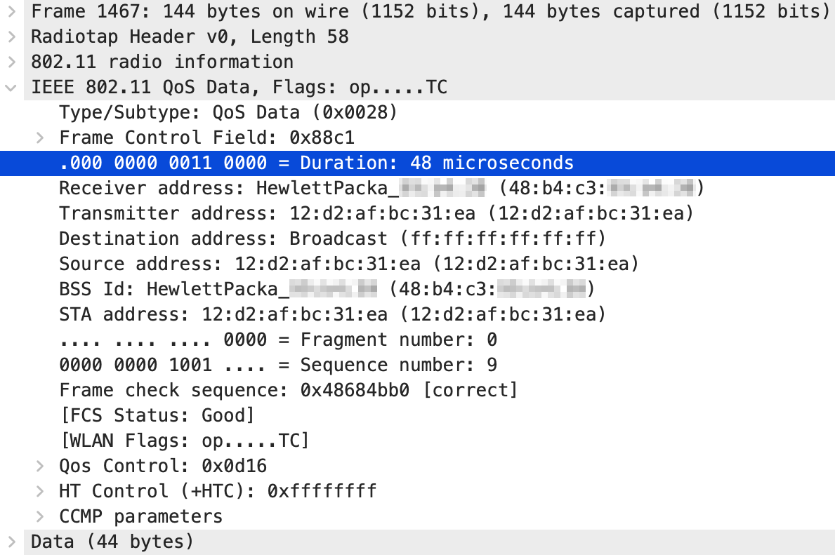
NAVはすべてのMACで提供されなければならない。
IEEE Std 802.11-2020, p.1641
A virtual CS mechanism, referred to as the NAV, shall be provided by all MACs.
NAVは、実際にデータをやり取りする前にSTAのRTS/CTS frameのDuration情報に基づいた将来のトラフィック予測を保持する。Duration情報はすべてのフレームのMACヘッダーからも参照できる。
IEEE Std 802.11-2020, p.1641
The NAV maintains a prediction of future traffic on the medium based on duration information that is announced in RTS/CTS frames by non-DMG STAs and RTS/DMG CTS frames by DMG STAs prior to the actual exchange of data. The duration information is also available in the MAC headers of all frames
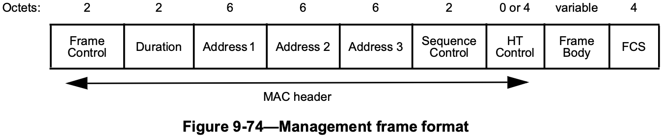
Durationの値は、例えば SIFS + Ack frameにかかる時間(μs) となってる。
CWNA Study Guide, p.281
For example, the duration value of the data frame in Figure 8.3 and 8.4 is an indication of the amount of time needed to respond to a unicast exchange with an ACK frame
もし Wi-Fi フレームが自身宛てだったら、 Duration フィールドは無視して NAV にセットしない。
IEEE Std 802.11-2020, p.1647
A STA that receives at least one valid frame in a PSDU can update its NAV with the information from any valid Duration field in the PSDU. When the received frame’s RA is equal to the STA’s own MAC address, the STA shall not update its NAV.
自分宛ならNAVをUpdateしてはいけない、自分宛以外でNAVが自分が持っている値より大きいなら、Updateしなければいけない。
IEEE Std 802.11-2020, p.1647
For all other received frames the STA shall update its NAV when the received Duration is greater than the STA’s current NAV value.
Physical CS 又は Virtual CS のどちらか片方でも BUSY と判定した場合に無線媒体は BUSY として扱われ、共に IDLE だと判定した場合にのみ無線媒体は IDLE として扱われる。
IEEE Std 802.11-2020, p.1641
- Physical and virtual CS functions are used to determine the state of the medium. When either function indicates a busy medium, the medium shall be considered busy; otherwise, it shall be considered idle.
IFS
IFS は Wi-Fi フレームと Wi-Fi フレームとの間の時間間隔のこと。 Wi-Fi 機器は Physical CS と Virtual CS を使って、 Wi-Fi フレーム送信前に IFS の時間だけ無線媒体が IDLE であることを確かめなきゃいけない。IEEE Std 802.11-2020 では 10 種類の IFS が定義されている。
IEEE Std 802.11-2020, p.1642
- The time interval between frames is called the IFS. A STA shall determine that the medium is idle through the use of the CS function for the interval specified. Ten different IFSs are defined to provide priority levels for access to the wireless medium.
- The IFSs are as follows:
- a) RIFS reduced interframe space
- b) SIFS short interframe space
- c) PIFS priority interframe space
- d) DIFS DCF interframe space
- e) AIFS[AC] AIFS arbitration interframe space (for the AC used by the QoS facility)
- f) EIFS extended interframe space
- g) SBIFS short beamforming interframe space
- h) BRPIFS beam refinement protocol interframe space
- i) MBIFS medium beamforming interframe space
- j) LBIFS long beamforming interframe space
各IFSの計算式
- SIFS = aSIFSTime
- RIFS = 2μs
- PIFS = SIFS + slot time
- DIFS = SIFS + 2 x slot time
- EIFS = SIFS + AckTXTime + DIFS
- AIFS = AIFSN(AC) x slot time + SIFS
IEEE 802.11ac (WI-Fi 5)を前提にすると、
- Short Interframe Space(SIFS): 16μs - Ack フレームや BlockAck フレームを送信する前
- DCF Interframe Space(DIFS): 34μs - Data フレームを送信する前
など、規格により各 IFS の値が定められている。 SIFS の値は PHY ごとに定められていて、5 GHz バンドなら 16μs 。 DIFS は SIFS + スロットタイム × 2 なので、5 GHz バンドなら 16 + 9 × 2 = 34μs になる。
具体的なSIFSとslot timeの数値は各PHYで決まってる。VHTだとどうなのか見てみる; Table 21-28には書かれていないので、Table 19-25(HT PHY)の値と同じ。
IEEE Std 802.11-2020, p.3118
The static VHT PHY characteristics, provided through the PLME-CHARACTERISTICS service primitive, shall be as shown in Table 19-25 unless otherwise listed in Table 21-28.
(IEEE Std 802.11-2020 - Table 19-25—HT PHY characteristics, p.2951 ※一部省略あり)
| Characteristics | Value |
|---|---|
| aSlotTime | 9 μs(5 GHz bands) |
| aSIFSTime | 16 μs(5 GHz bands) 10 μs(2.4 GHz bands) |
| aCWmin | 15 |
| aCWmax | 1023 |
上に示したパケットキャプチャの画像にある Duration フィールドの値: 48μs は、SIFS と Ack フレームの 送信にかかる時間の合計を QoS Data フレームの送信者が計算した値。
下の画像は EAPOL の 4-way handshake をキャプチャしたもので、Data フレームと、それに対する Ack フレームが交互に並んでる。

Data フレームと Ack フレームの時間差は 22μs・25μs・28μs・29μs とばらついていて、SIFS の 16μs ぴったりにはならない。キャプチャのタイムスタンプの精度とか電波状況の影響を受けるから。 ただ、どれも DIFS の 34μs より短い。もし Ack フレームが DIFS + Random Backoff を待ってから 送信されてるなら、フレームとフレームの間隔が 34μs より短くなることはない。 つまり、Ack フレームが SIFS の後に送信されてることは、このキャプチャからも分かる。
Random Backoff
Random Backoff はランダムに決まる待機時間。Contention Window(CW)の範囲(0〜CW)からランダムに選ばれた整数値と各 PHY 層で定められたスロットタイム を掛けた値。
IEEE Std 802.11-2020, p.1671
Backoff Count = Random() (10-1)
where
Random() = Pseudorandom integer drawn from a uniform distribution over the interval [0,CW],
where CW is an integer within the range of values of the PHY characteristics aCWmin and aCWmax, aCWmin ≦ CW ≦ aCWmax.
NOTE—It is important that designers recognize the need for statistical independence of the random number streams between STAs.
Data フレームか Management フレームを送信する前に実行されるので、 Control フレーム(Ack フレームとか)は対象外。IFS と同じで Physical CS と Virtual CS を使って、Random Backoff の間、無線媒体が IDLE であることを確かめなきゃいけない。IFS が終了した後に Random Backoff を実行することで、同じ種類のフレームを送信しようとする複数の Wi-Fi 機器が同時にフレームを送信する可能性が下がるので、フレームの衝突(Collision)が発生する確率も下がる。
IEEE Std 802.11-2020, p.1671
A STA desiring to initiate transfer of Data frames and/or Management frames using the DCF shall invoke the CS mechanism (see 10.3.2.1) to determine the busy/idle state of the medium. If the medium is busy, the STA shall defer until the medium is determined to be idle without interruption for a period of time equal to EIFS when the last transition to idle medium was a result of a frame detected on the medium that was not received correctly, or equal to DIFS otherwise. After this DIFS or EIFS medium idle time, the STA shall then generate a random backoff count [defined by Equation(10-1)] for an additional deferral time before transmitting, unless the backoff counter already contains a nonzero value, in which case the selection of a random number is not needed and not performed. This process minimizes collisions during contention between multiple STAs that have been deferring to the same event.
IEEE 802.11ac なら、スロットタイムは 9μs で、フレーム送信が初回であれば CW は 15(CWmin)。 CW はフレームの再送ごとに増加していくけど、1023(CWmax)が最大値。 どれも上に載せた Table 19-25 の値。(IEEE Std 802.11-2020 - Table 19-25, p.2951)
IEEE Std 802.11-2020, p.1671-1672
- The contention window (CW) parameter shall take an initial value of aCWmin.
- The CW shall take the next value in the series every time an unsuccessful attempt to transmit an MPDU causes either STA retry count to increment, until the CW reaches the value of aCWmax.
- This improves the stability of the access protocol under high-load conditions.
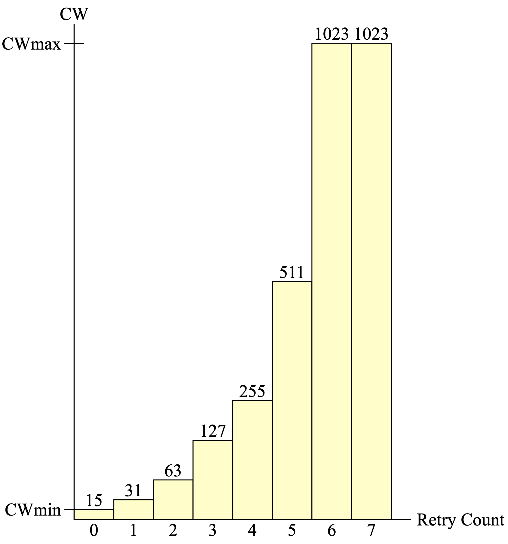
CWの値は、フレームの送信が成功したり、再送回数の上限まで再送したら初期化される。
IEEE Std 802.11-2020, p.1672
The CW shall be reset to aCWmin after every successful attempt to transmit a Data or Management frame, or when SSRC reaches dot11ShortRetryLimit.
backoff procedureを実行してるSTAは、backoff slotの間CSをしてMediumがBUSYかどうか判断する。 もしその間IDLEだったなら、backoff counterを減らす。
IEEE Std 802.11-2020, p.1673
A STA performing the backoff procedure shall use the CS mechanism (see 10.3.2.1) to determine whether there is activity during each backoff slot. If no medium activity is indicated for the duration of a particular backoff slot, then the backoff procedure shall decrement its backoff counter.
backoff counterが0になったら送信を始めなければいけない。
IEEE Std 802.11-2020, p.1674
Transmission shall commence when the backoff counter equals 0.
backoff procedureによって複数のSTAがrandom backoffする → 最小のbackoff countを使うSTAが競合に勝つ。 (隠れ端末問題があるので必ずそうとも限らないけど)
IEEE Std 802.11-2020, p.1674
The effect of this procedure is that when multiple STAs are deferring and go into random backoff, then the STA selecting the smallest backoff count using the random function wins the contention (assuming all of the contending STAs detect the same instances of WM activity at their respective receivers, a situation that is not always true, due to hidden node effects and interference events).
backoff counterの値は保持できて、再度IDLEになったら続きから値を減らせる。
IEEE Std 802.11-2020, p.1674
If the medium is determined to be busy at any time during a backoff slot, then the backoff counter shall not be decremented for that slot. The backoff counter is next decremented after the medium has been determined to be idle for the duration of a DIFS or EIFS, as appropriate (see 10.3.3 and 10.3.2.3.7), plus aSlotTime.
CWNA Study Guide, p.283
If the physical or virtual carrier sense mechanisms sense a busy medium, the backoff timer decrement is suspended and the backoff timer value is maintained. When the medium is idle for a DIFS period, the backoff process resumes and continues the countdown from where it left off.
Ackが必要なフレームを送信した後は、Ackの手順に従わないといけない。 MACフレーム(MPDU)の送信失敗ごとに、Data/ManagementフレームでかつRTSThreshold以下の長さのフレームならSRCを増加しないといけない。 再送フレームなら、Retryサブフィールドを"1"にセットしないといけない。 フレームの再送は、dot11ShortRetryLimit か dot11MaxTransmitMSDULifetime まで続く。
IEEE Std 802.11-2020, p.1676
-
After transmitting a frame that requires immediate acknowledgment, the STA shall perform the acknowledgment procedure, as defined in 10.3.2.11. The SRC for an MPDU with the Type subfield equal to Data or Management and of length less than or equal to dot11RTSThreshold and the SSRC shall be incremented every time transmission of that MPDU fails.
(SRC: Short Retry Count, SSRC: STA Short Retry Count) -
All retransmission attempts for an MPDU with the Type subfield equal to Data or Management that has failed the acknowledgment procedure one or more times shall be made with the Retry subfield set to 1.
-
Retries for failed transmission attempts shall continue until the SRC for the MPDU with the Type subfield equal to Data or Management is equal to dot11ShortRetryLimit or until the transmit MSDU timer for the MSDU or any undelivered fragments of that MSDU exceeds dot11MaxTransmitMSDULifetime (see 10.4).
再送されたフレームでは、MAC ヘッダーの Frame Control フィールドにある Retry サブフィールドが "1" になっている。再送してもフレームに割り当てられた Sequence number は変わらないので、 元のフレームと同じ値(この画像だと 1)が入る。
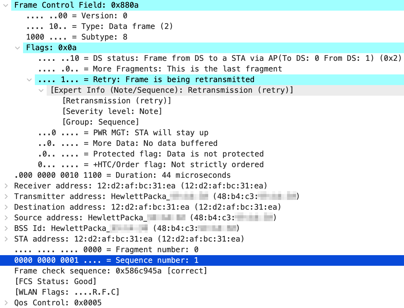
dot11ShortRetryLimit のデフォルト値は 7 。ちなみに、 dot11LongRetryLimit のデフォルト値は 4; Long か Short の違いは dot11RTSThreshold を超えるかどうかで決まるみたい。
IEEE Std 802.11-2020, p.3891
dot11ShortRetryLimit OBJECT-TYPE
    SYNTAX Unsigned32 (1..65535)
    MAX-ACCESS read-write
    STATUS current
    DESCRIPTION
        "This is a control variable.
        It is written by an external management entity.
        Changes take effect as soon as practical in the implementation.
        This attribute indicates the maximum number of transmission attempts of a
       frame that are made before a failure condition is indicated."
    DEFVAL { 7 }
    ::= { dot11OperationEntry 3 }

dot11LongRetryLimit OBJECT-TYPE
    SYNTAX Unsigned32 (1..255)
    MAX-ACCESS read-write
    STATUS deprecated
    DESCRIPTION
        "Deprecated as the related feature has been removed from IEEE Std 802.11.
        This is a control variable.
        It is written by an external management entity.
        Changes take effect as soon as practical in the implementation.
        This attribute indicates the maximum number of transmission attempts of a
        frame, in a PSDU of length that is greater than dot11RTSThreshold, that is
        made before a failure condition is indicated."
    DEFVAL { 4 }
    ::= { dot11OperationEntry 4 }
EDCA, WMM
EDCA
Wi-Fi 通信に QoS 機能を導入するために、IEEE Std 802.11e-2005 において EDCA が定義された。 IEEE Std 802.11-2020 - 10.23.2 では、4 つの独立した Enhanced Distributed Channel Access Functions(EDCAFs)を DCF に追加したものが EDCA であるって書かれてる。なので、基本は DCF で QoS の部分を 追加したのが EDCA 。
IEEE Std 802.11-2020, p.1737
The EDCA channel access protocol is derived from the DCF procedures described in 10.3 by adding four independent enhanced distributed channel access functions (EDCAFs) to provide differentiated priorities to transmitted traffic, through the use of four different access categories (ACs).
優先順位で4つに分けるっていう部分がDCFとの大きな違い。
CWAP Official Study Guide (CWAP-404), p.337
This variation in random backoff times based on frame priority as a key differentiation between DCF and EDCA.
EDCA では、上位層から受け取った MAC Service Data Unit(MSDU)が User Priority(UP)の値をもとに 4 つの Access Category(AC)にマッピングされ、各 AC に対応したそれぞれの EDCAF が無線媒体の競合に使われる。
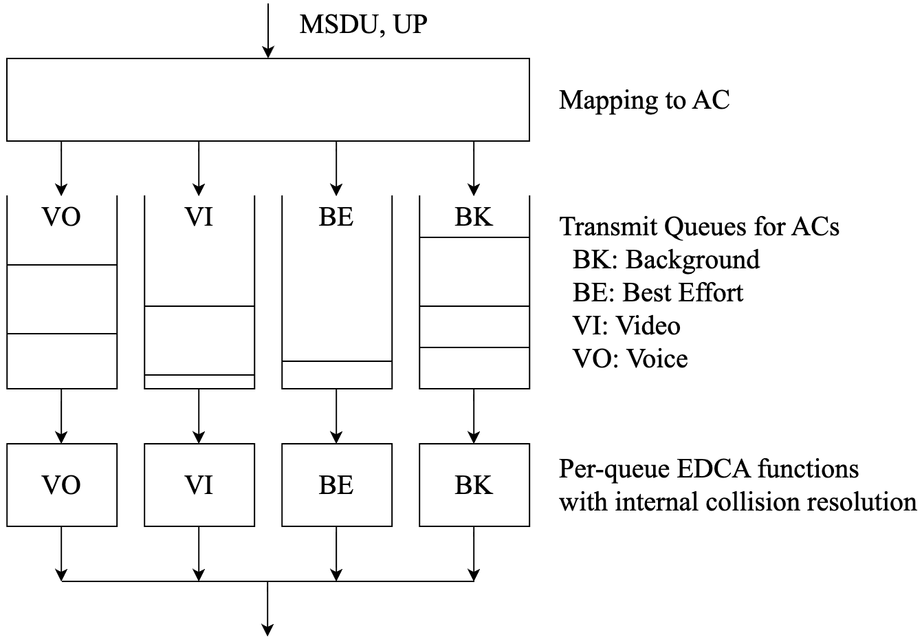
UP の値は、QoS Data フレームの QoS Control フィールドにある TID として示される。
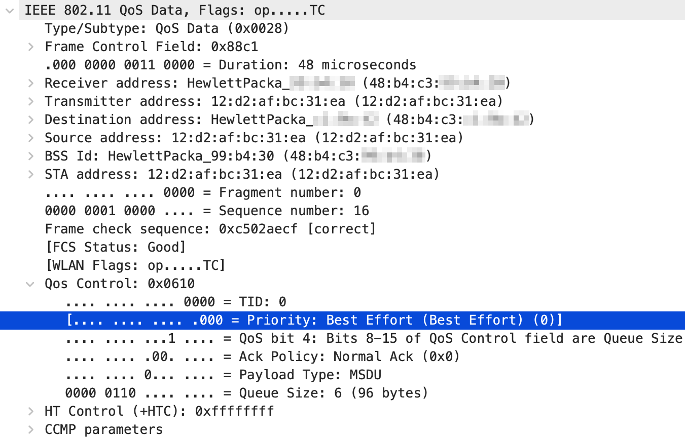
この QoS Data フレームは TID が 0 なので、AC_BE にマッピングされる。 Wireshark は TID に対応する UP も表示してくれる。
EDCA では Transmit Opportunity(TXOP)も導入されていて、CSMA/CA のように Wi-Fi フレーム 1 つの送信権を 与えられるのではなくて、無線媒体を占有できる一定時間が付与される場合がある。 TXOP の間は、SIFS を挟みつつ複数のフレームを連続して送信できる。
CWNA Study Guide, p.286
The DCF medium-contention mechanisms discussed earlier allow for an 802.11 radio to transmit a single frame. After transmitting a frame, the 802.11 station must contend for the medium again before transmitting another frame. HCF defines the ability for an 802.11 radio to send multiple frames when transmitting on the RF medium. When an HCF-compliant radio contends for the medium, it receives an allotted amount of time to send frames. This period of time is called a transmit opportunity (TXOP). During this TXOP, an 802.11 radio may send a single frame or multiple frames. During the TXOP, multiple frames can be sent sequentially in what is called a frame burst. A short interframe space (SIFS) is used between each frame to ensure that no other radios transmit during the frame burst. However, frame aggregation is the more common method to send multiple frames during a TXOP. Frame aggregation is a method of combining multiple frames into a single frame transmission during a TXOP.
各ACごとで、EDCAFがTXOPを勝ち取るために競合する。
CWNA Study Guide, p.287
For each access category, an enhanced version of DCF known as Enhanced Distributed Channel Access Function (EDCAF) is used to contend for a TXOP.
WMM
Wi-Fi Multimedia (WMM) は、IEEE Std 802.11e-2005 で定義された機能の一部に基づいた、Wi-Fi 通信における QoS
機能の実装規格。 HCF として EDCA のみを使う。
→ 802.11eでは、実装されることがないいろんな技術・機能が規定されているけど、Wi-FiにQoS自体は実装するべきで、そのために802.11eのいいとこだけを取ってWMMが規格化された。
Wi-Fi Multimedia™ Technical Specification Version 1.2.0, p.7
This document defines the specification for WMM, an 802.11 QoS implementation based on a subset of the draft IEEE 802.11e standard supplement [2]. It was originally motivated by the need to prevent market fragmentation caused by multiple, non-interoperable pre-standard subsets of the draft 802.11e standard that would otherwise occur. Deployment of WMM will deliver useful QoS functionality for services such as voice over 802.11 and streaming media.
CWNA Study Guide, p.48
The 802.11e amendment defines enhanced medium access methods to support QoS requirements. Hybrid Coordination Function (HCF) is an additional coordination function that is applied in an 802.11e QoS wireless network. HCF has two access mechanisms to provide QoS. Enhanced Distributed Channel Access (EDCA) is an extension to DCF.
WMM Parameters
AC ごとにデフォルト WMM パラメーターとして CWmin・CWmax・TXOP Limit・Arbitration Inter Frame Spacing Number(AIFSN)の値を定めてて、 AC_VO・AC_VI・AC_BE・AC_BK の順でフレーム送信が優先されるにとなってる。下の表は、 WMM Specification p.24 で示されてるデフォルト WMM パラメーター。
| AC | CWmin | CWmax | AIFSN | TXOP Limit (802.11b) | TXOP Limit (802.11a/g) |
|---|---|---|---|---|---|
| AC_BK | aCWmin | aCWmax | 7 | 0 | 0 |
| AC_BE | aCWmin | aCWmax | 3 | 0 | 0 |
| AC_VI | (aCWmin + 1)/2 - 1 | aCWmin | 2 | 6.016ms | 3.008ms |
| AC_VO | (aCWmin + 1)/4 - 1 | (aCWmin + 1)/2 - 1 | 2 | 3.264ms | 1.504ms |
aCWmin と aCWmax の値は、VHT PHY 仕様を見ても載ってなくて、HT PHY と同じ値。 (IEEE Std 802.11-2020 - Table 19-25—HT PHY characteristics, p.2951 ※一部省略あり)
| Characteristics | Value |
|---|---|
| aCWmin | 15 |
| aCWmax | 1023 |
表の値はあくまでデフォルト値で、アクセスポイントによっては変更できることもある。 実際に使用する WMM パラメーターは、Wi-Fi 接続時のネゴシエーションにより決定されて、 WMM アソシエーションが確立することによって、互いに QoS Data フレームを送信できるようになる。
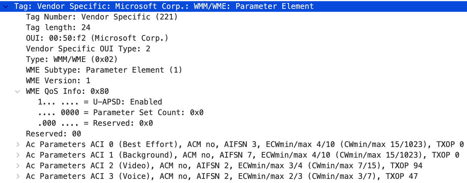
アクセスポイントは、Beacon フレームの WMM Parameter Element で実際に使う WMM パラメーターを 通知してる。
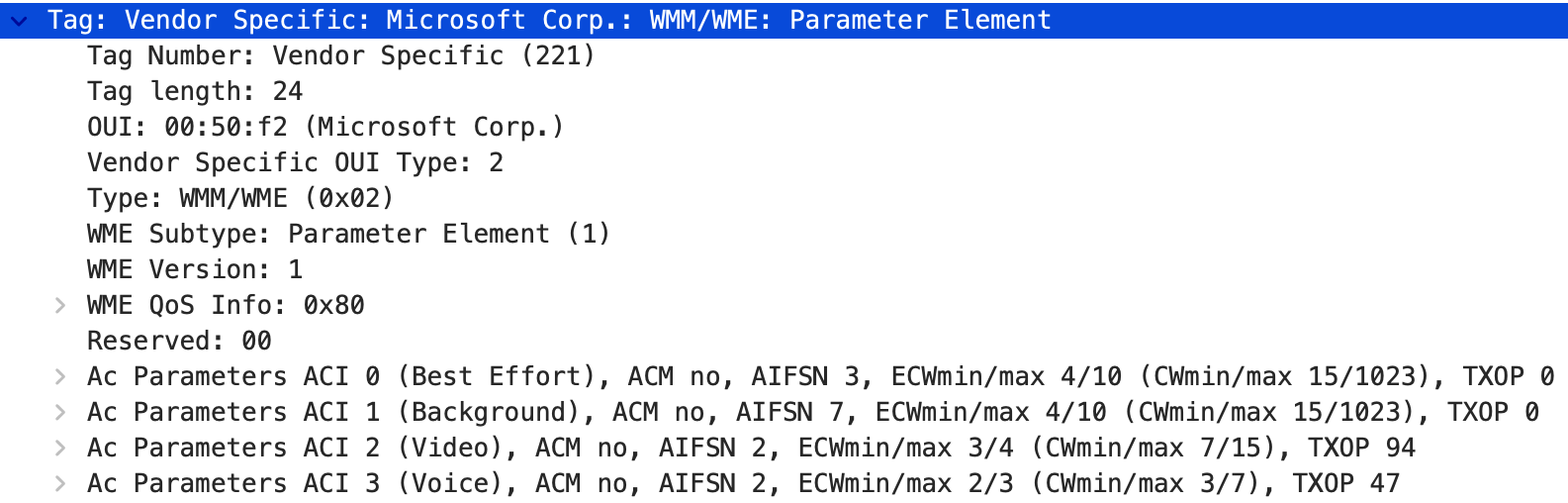
ECWmin・ECWmax は指数で示されていて、CW = 2ECW - 1 の関係。ECWmin/max が 4/10 なら CWmin/max は 15/1023 で、Wireshark が括弧の中に換算後の値も出してくれてる。
IEEE Std 802.11-2020, p.1069
The ECWmin and ECWmax subfields encode the values of CWmin and CWmax, respectively, in an exponent form. The ECWmin and ECWmax values are defined so that
TXOP Limit の単位は 32μs なので、AC_VI の TXOP 94 は 94 × 32μs = 3.008ms、 AC_VO の TXOP 47 は 47 × 32μs = 1.504ms 。
CWAP Official Study Guide (PW0-270), p.257
TXOP limits are set in intervals of 32 microseconds, and they are configured individually for each AC. That means that if an AP has the voice AC configured for a TXOP limit of 47 (which happens to be the default value specified in 802.11e), then all traffic using the voice AC will be allocated a TXOP of up to 1,504 microseconds whenever access to the channel is won.
このアクセスポイントは、上の表のデフォルト値(TXOP Limit は 802.11a/g の列)どおりの値を使ってた。
AC parameter set count は、WMM parameter が変わるたびに 1 ずつ足される。
Wi-Fi Multimedia™ Technical Specification Version 1.2.0, p.24
The AC parameter set count that is contained in the WMM Parameter Element and WMM Information Element is incremented following the change of one or multiple WMM parameters.
STA は Beacon の WMM Parameter Element で通知される WMM Parameters をモニターして、変化に応じて 自分の値をアップデートしないといけない。association 前の段階では、これらの値を Table 13 の デフォルト値にセットしないといけない。
Wi-Fi Multimedia™ Technical Specification Version 1.2.0, p.24
The STA is required to monitor the change of WMM parameters conveyed in the WMM Parameter Element in beacons and shall update its values accordingly. Prior to association (and used only for transmitting probe, authentication and association request frames) it shall set these parameters to the default values shown in Table 13.
その後は、Probe Response フレーム・Association Response フレーム・アソシエーションしてる AP の Beacon フレームから受け取った WMM Parameters でアップデートしないといけない。 無線媒体にアクセスするときに現時点の WMM Parameters を使うことは、STA の義務。
Wi-Fi Multimedia™ Technical Specification Version 1.2.0, p.24
A STA shall subsequently update the values of these parameters from any successfully received probe response frame, association response frame, which are addressed to the STA or beacon frame transmitted by the AP with which the STA is associated. It is the responsibility of the STA to use the current WMM parameters for accessing the wireless medium.
AP は、advertise してる値とは違う値を使うことができる。AP が使う推奨のデフォルト値は Table 15 に あって、AP の場合は AIFSN が 1 以上でないといけない。
Wi-Fi Multimedia™ Technical Specification Version 1.2.0, p.24
The AP may use a different set of parameters than it advertises. A recommended set of default parameters for the AP is listed in the annex. The value of AIFSN shall be greater than or equal to 1 for APs.
なので、AP 自身は Table 15 の値を使って、STA に通知するのは Table 13 の値、というのが推奨。
Wi-Fi Multimedia™ Technical Specification Version 1.2.0, p.39
It is recommended that the AP uses the default EDCA parameter listed in Table 15 and advertises the Table 13 values in WMM Parameter Elements.
(Wi-Fi Multimedia™ Technical Specification Version 1.2.0 - Table 15 Default EDCA Parameters for the AP)
| AC | CWmin | CWmax | AIFSN | TXOP Limit (802.11b) | TXOP Limit (802.11a/g) |
|---|---|---|---|---|---|
| AC_BK | aCWmin | aCWmax | 7 | 0 | 0 |
| AC_BE | aCWmin | 4*(aCWmin + 1) - 1 | 3 | 0 | 0 |
| AC_VI | (aCWmin + 1)/2 - 1 | aCWmin | 1 | 6.016ms | 3.008ms |
| AC_VO | (aCWmin + 1)/4 - 1 | (aCWmin + 1)/2 - 1 | 1 | 3.264ms | 1.504ms |
Table 13 と比べると、AC_BE の CWmax が広がってて、AC_VI と AC_VO の AIFSN が 2 から 1 に なってる。AP の方が待ち時間が短くて、フレームを送信しやすい値。
AP が自分を優先するのは、無線媒体を流れるフレームは AP からクライアント宛てのものが一番多いから。
CWAP Official Study Guide (CWAP-404), p.341
Also note that, with allowance by WMM, the AP may use different parameters than it advertises for the clients to use. This allows the AP to grant itself greater priority given that the greatest volume of frames on the medium are AP-to-client and not client-to-AP. Again, this is allowed in the WMM specification.
QoS の情報がない Data フレームは Best Effort として扱われる。Management フレームには QoS Control フィールドがないけど、AC_VO のパラメーターで送信するべきとされてる。
Wi-Fi Multimedia™ Technical Specification Version 1.2.0, p.25
Data frames with no priority information are treated as best effort. Management frames have no QoS Control field, but should be transmitted with parameters of AC_VO
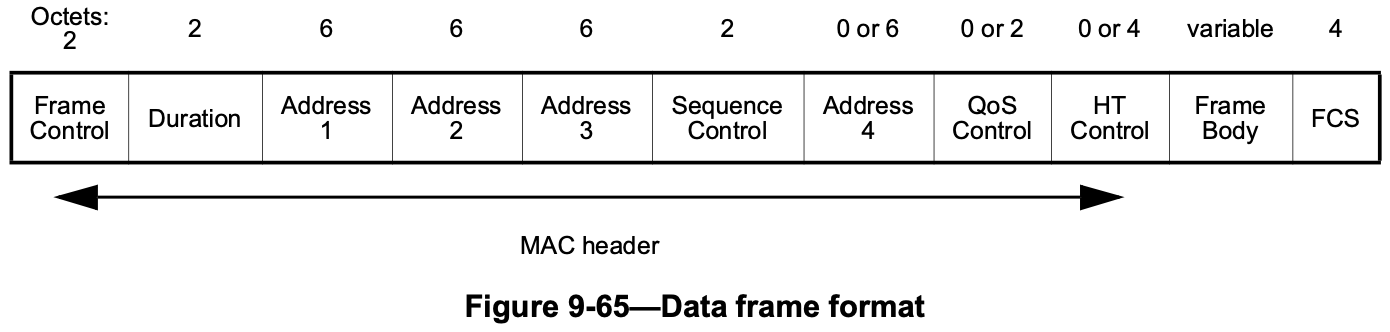
WMM Association
Frame Format
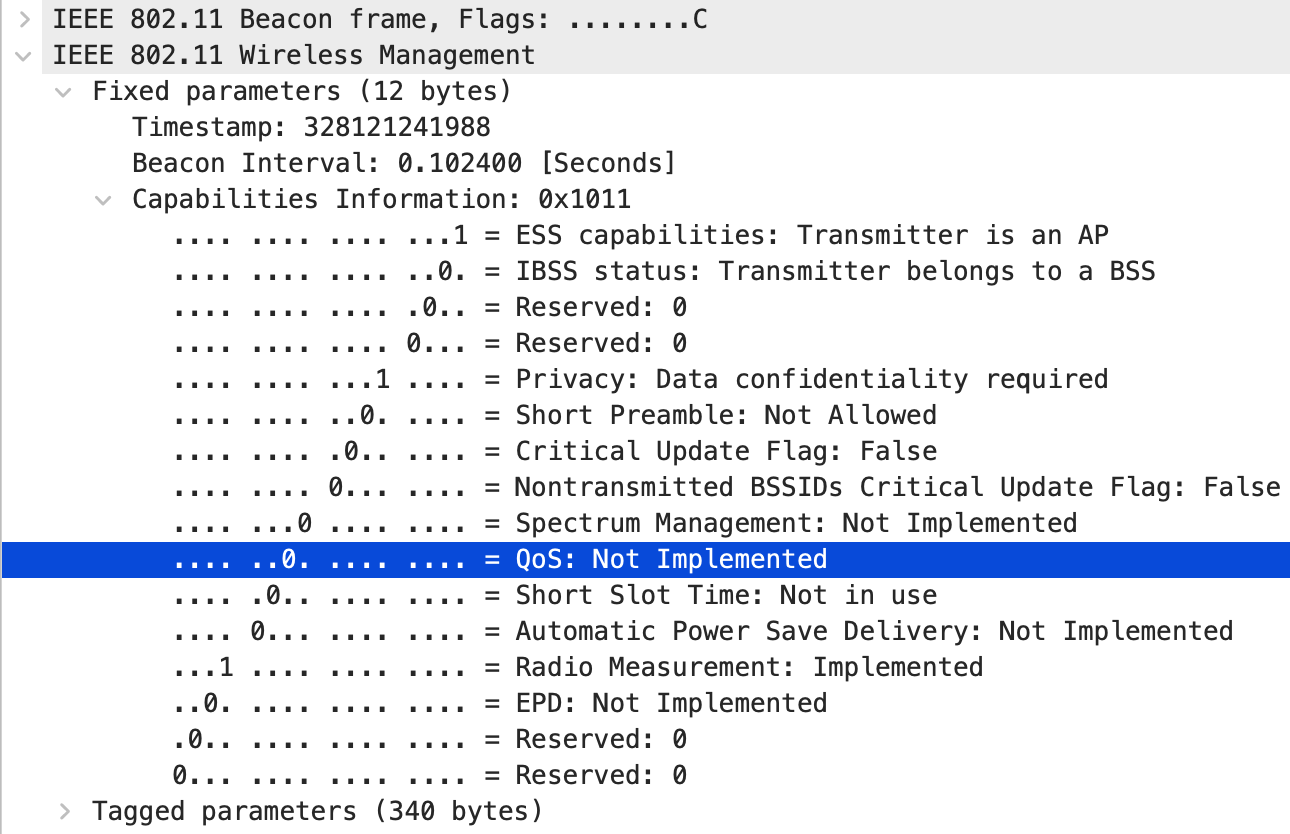
WMM だけに対応してる AP や STA は、Association・Beacon・Probe Response フレームの Capability Information フィールドにある QoS ビットをセットしない。かわりに、WMM Information Element が この規格で新しく定義されていて、それらのフレームで運ばれる。
Wi-Fi Multimedia™ Technical Specification Version 1.2.0, p.9
A WMM-only AP or STA does not set the "QoS" bit in the capability field of association, beacon and probe response frames. A new WMM Information Element is defined in this specification and is carried in those frames.
Aruba の AP も Buffalo の無線 LAN ルーターも QoS ビットは 0 (デフォルト; 変更できるかは不明)。
実際のフレーム
Beacon フレームと Probe Response フレームの WMM Parameter Element フィールドの中で、 QoS でどんなパラメーターを使うか伝えてる。
実際のフレーム
(Wi-Fi Multimedia™ Technical Specification Version 1.2.0 - Table 5 WMM Parameter Element Field Values)
| Field | Value |
|---|---|
| Element ID | 221 |
| Length | 24 |
| OUI | 00:50:f2 (hex) |
| OUI Type | 2 |
| OUI Subtype | 1 |
| Version | 1 |
| QoS Info field | See Figure 6 and Figure 7 |
| Reserved | 0 |
| AC Parameters Best_Effort | AC Parameters Record AC_BE |
| AC Parameters Background | AC Parameters Record AC_BK |
| AC Parameters Video | AC Parameters Record AC_VI |
| AC Parameters Voice | AC Parameters Record AC_VO |
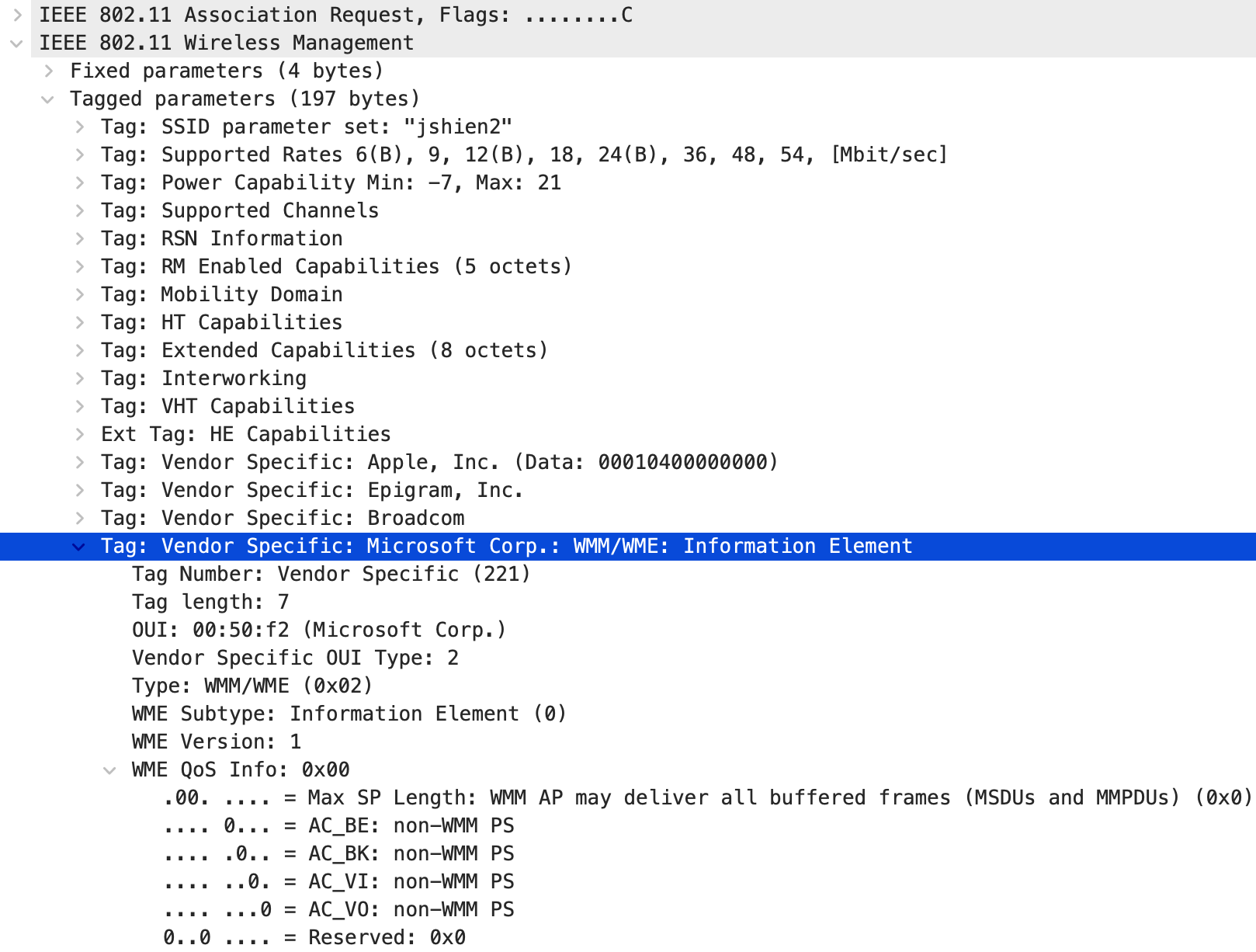
Association Request フレームの WMM Information Element フィールドで、STA 自身が WMM を サポートしていることを伝える。
(Wi-Fi Multimedia™ Technical Specification Version 1.2.0 - Table 3 WMM Information Element Field Values)
| Field | Value |
|---|---|
| Element ID | 221 |
| Length | 7 |
| OUI | 00:50:f2 (hex) |
| OUI Type | 2 |
| OUI Subtype | 0 |
| Version | 1 |
| QoS Info field | See Figure 6 and Figure 7 |
QoS Info field の中身は、WMM AP から送信されるときと WMM STA から送信されるときで違う。
(Wi-Fi Multimedia™ Technical Specification Version 1.2.0 - Figure 6 QoS Info field when sent from WMM AP)
| Bit | 7 | 6〜4 | 3〜0 |
|---|---|---|---|
| サブフィールド | U-APSD | Reserved | Parameter Set Count |
(Wi-Fi Multimedia™ Technical Specification Version 1.2.0 - Figure 7 QoS Info field when sent from WMM STA)
| Bit | 7 | 6〜5 | 4 | 3 | 2 | 1 | 0 |
|---|---|---|---|---|---|---|---|
| サブフィールド | Reserved | Max SP Length | Reserved | AC_BE U-APSD Flag | AC_BK U-APSD Flag | AC_VI U-APSD Flag | AC_VO U-APSD Flag |
実際のフレーム
Negotiation
-
Beacon フレーム: WMM が使える AP は WMM Information Element フィールド or WMM Parameter Element フィールドを追加しないといけない
Wi-Fi Multimedia™ Technical Specification Version 1.2.0, p.16
Every beacon frame transmitted by a WMM-enabled AP shall contain, in addition to those elements specified in [1], either a WMM Information Element or a WMM Parameter Element.
※ [1]: ISO/IEC 8802-11:1999(E) ANSI/IEEE Std 802.11, 1999 Reaffirmed 2003 edition
-
Probe Request フレーム: 変更なし
Wi-Fi Multimedia™ Technical Specification Version 1.2.0, p.16
Probe request frames transmitted by a WMM-enabled STA are unchanged from [1].
-
Probe Response フレーム: WMM が使える AP は WMM Parameter Element フィールドを追加しないといけない
Wi-Fi Multimedia™ Technical Specification Version 1.2.0, p.16
A probe response frame transmitted by a WMM-enabled AP shall contain a WMM Parameter Element.
-
Association Request フレーム: WMM を使う STA は WMM Information Element フィールドを追加しないといけない
Wi-Fi Multimedia™ Technical Specification Version 1.2.0, p.17
A WMM association request frame contains a WMM Information Element in addition to the information elements specified in [1].
-
Association Response フレーム: Association Request フレームに WMM Information Element フィールドがあったなら WMM Parameter Element フィールドを追加しないといけない。逆に Association Request フレームに WMM Information Element フィールドがなかったなら WMM Parameter Element フィールドを追加してはいけない
Wi-Fi Multimedia™ Technical Specification Version 1.2.0, p.17
An association response frame shall contain a WMM Parameter Element in addition to the information specified elements in [1] if the corresponding association request contained a WMM Information element and shall not contain a WMM Parameter Element if the corresponding association request did NOT contain a WMM Information element.
原文のミスと修正
原文(2.2.7 Association Response Frame)には 2 箇所ミスがある。
[1]の位置がError! Reference source not found.になってるのと、association requestがssociation requestになってるところ。 前者は他の節が全部[1]なのでそう推測して、後者は誤字として直した。the information specified elementsの語順は原文のまま
WMM をサポートする AP は、WMM Information Element or WMM Parameter Element を Beacon に 含めないといけない。Probe Response には、WMM Parameter Element を含めないといけない。
Wi-Fi Multimedia™ Technical Specification Version 1.2.0, p.23
An AP that supports WMM shall include either a WMM Information Element or a WMM Parameter Element in its beacon. In response to a probe request, a WMM-enabled AP shall include a WMM Parameter Element in its probe response.
Association Request に WMM Information Element が含められていたら、AP が Association Response を 返すときに WMM Parameter Element を含めてなければいけない、かつ WMM association として 扱わなければいけない。
Wi-Fi Multimedia™ Technical Specification Version 1.2.0, p.23
On receipt of an association request and subsequent transmission of a corresponding association response: the AP shall include a WMM Parameter Element in the association response if the corresponding association request contained a WMM Information element and shall treat the association as a WMM association.
WMM association をした STA 宛てに Data フレームを送信するときは、AP は (WMM) QoS Data フレームを 使わないといけない。WMM association じゃないなら、QoS Data フレームを使ってはいけない。
Wi-Fi Multimedia™ Technical Specification Version 1.2.0, p.23
If the destination address of a data frame to be transmitted on the wireless medium corresponds to a STA associated as a WMM association, the AP shall use WMM QoS data subtype frame formats when transmitting the frame to it. If the destination address corresponds to a STA associated as a non-WMM STA, the AP shall not use QoS data subtype frames.
WMM に対応してる STA は、Association Request を送信する前に、Beacon とか Probe Response に よって、AP が WMM に対応しているかを特定しないといけない。最も新しい Probe Response や Beacon によって特定しないといけない。
Wi-Fi Multimedia™ Technical Specification Version 1.2.0, p.23
A WMM-enabled STA shall determine the WMM capability of an AP with which it wishes to associate before transmitting an association request to it. It may do this either passively, by receiving a beacon frame, or actively, by transmitting a probe request to it. From the most recently received probe response or beacon from a specific AP, the STA shall determine whether the AP supports WMM.
AP が WMM に対応してると特定できたなら、STA は Association Request に WMM Information Element を 含めないといけない。かつ Association Response に WMM Parameter Element が含まれてたら WMM association として扱わないといけない。
Wi-Fi Multimedia™ Technical Specification Version 1.2.0, p.23
A STA shall include a WMM Information Element in an association request if it has determined that the recipient AP supports WMM and shall treat the association as a WMM association if the association response contained a WMM Parameter element.
Frame Aggregation
IEEE Std 802.11n-2009 でフレームアグリゲーション機能として、Aggregate MAC Service Data Unit (A-MSDU)と Aggregate MAC Protocol Data Unit(A-MPDU)が導入された。 どっちも TXOP を使うのが前提で、Wi-Fi 5(IEEE 802.11ac)以降の規格でもサポートされてる。
ちなみに、IEEE Std 802.11-2020 - 10.23.2.9 では、TXOP Limit が 0 でも A-MSDU か A-MPDU が 1 つなら送信できるって書かれてる。
IEEE Std 802.11-2020, p.1749
A TXOP limit of 0 indicates that the TXOP holder may transmit or cause to be transmitted (as responses) the following within the current TXOP:
-
a) One of the following at any rate, subject to the rules in 10.6
- 2) An SU PPDU or a VHT MU PPDU carrying a single MSDU, a single MMPDU, a single A-MSDU, or a single A-MPDU
A-MSDU
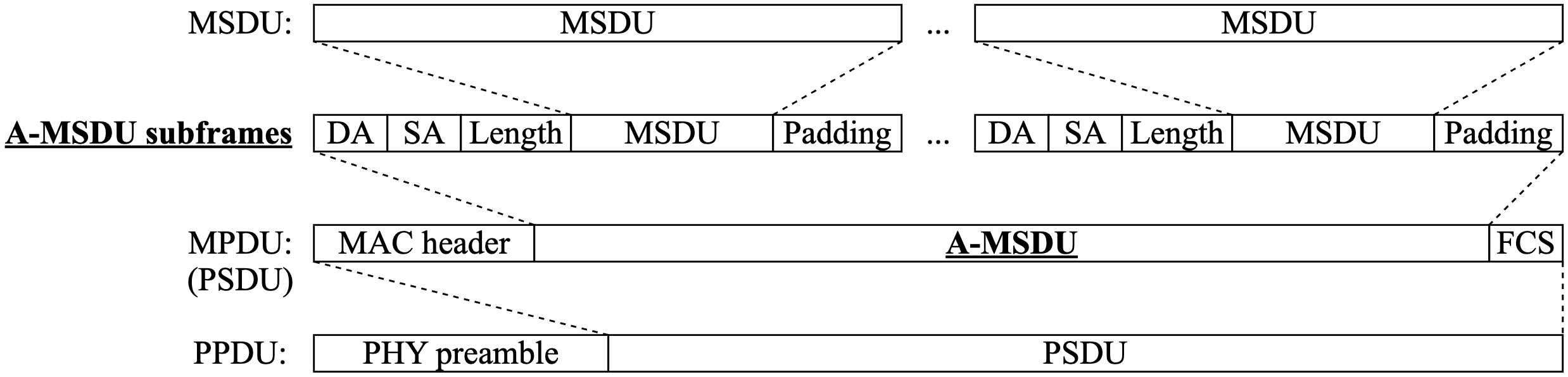
A-MSDU ( Aggregate MAC Service Data Unit )は、複数の MSDU を結合して 1 つの MAC Protocol Data Unit(MPDU)に含めることでフレーム送信のオーバーヘッドを減らす。 1つのMACヘッダーとFCSに対して複数のFrame bodyが入ってるイメージで。 1回のMACフレーム送信で多くのデータを送信できるから、オーバーヘッドを削減できるのがメリット。 弱点は、再送になったときに全部を再送しないといけないこと。
MSDU を結合するには、すべての MSDU が下の 3 つを満たしてないといけない。
- 同一の AC
- 同一の RA
- 同一の Transmitter Address(TA)
A-MSDU では複数の MSDU に対して 1 つの MAC ヘッダーと FCS が追加されるので、 FCS エラーが発生したら A-MSDU 全体を再送しなきゃいけない。 ACK として必要になるのは通常の Ack フレーム。
Format
IEEE Std 802.11-2020 では、A-MSDU の Format が下図のように定義されてる。 Padding は、A-MSDU サブフレームが "4 の倍数" bytes になるように調整するためのもの。
Frame body に A-MSDU subframes が入る。

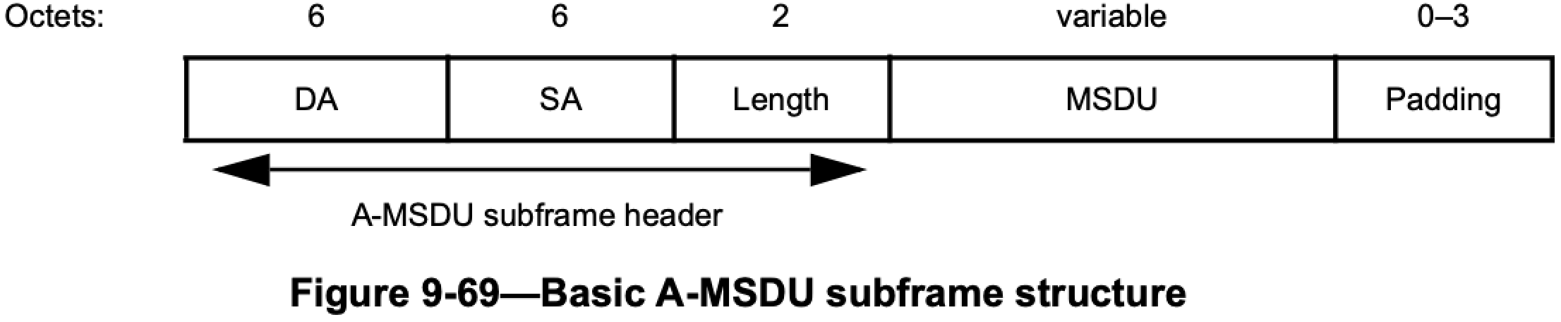
A-MSDU は、A-MSDU サブフレームが連続したもの。A-MSDU サブフレームは、 A-MSDU サブフレームヘッダー + MSDU + パディングで構成される。
IEEE Std 802.11-2020, p.818
An A-MSDU is a sequence of A-MSDU subframes as shown in Figure 9-68. Each A-MSDU subframe consists of an A-MSDU subframe header followed by an MSDU and 0 to 3 octets of padding as shown in Figure 9-69 (in 9.3.2.2.2), Figure 9-71 (in 9.3.2.2.3), and Figure 9-72 (in 9.3.2.2.4).
Basic A-MSDU サブフレームでは、(最後を除く) それぞれの A-MSDU サブフレームは 4 バイトの倍数に なるようにパディングが追加される。最後の A-MSDU サブフレームにはパディングは追加されない。
IEEE Std 802.11-2020, p.819
In the Basic A-MSDU subframe, each A-MSDU subframe (except the last) is padded so that its length is a multiple of 4 octets. The last A-MSDU subframe has no padding.
A-MSDU サブフレームヘッダーには、DA・SA・Length(MSDU の長さ)の 3 つのフィールドがある。
IEEE Std 802.11-2020, p.819
The A-MSDU subframe header contains three fields: DA, SA, and Length.
A-MSDU は、DA と SA の値が同じ RA と TA の値に対応する MSDU だけを含む。 ほぼ、DA = RA かつ SA = TA のときだけ、と考えてもいいかも。
IEEE Std 802.11-2020, p.819
An A-MSDU contains only MSDUs whose DA and SA parameter values map to the same receiver address (RA) and transmitter address (TA) values.
A-MSDU の構造は、1 つの MPDU (= MAC フレーム) の Frame body の中に含められる。 もし暗号化されてたら、MPDU は 1 つのユニットとして暗号化される。
IEEE Std 802.11-2020, p.819
The A-MSDU structure is contained in the frame body of a single MPDU. If encrypted, the MPDU is encrypted as a single unit.
下の画像は、ns-3 のシミュレーション(BE_MaxAmsduSize = 7935)で取得した QoS Data フレームの
A-MSDU 部分。UDP ペイロード 1472 bytes の MSDU が 5 つ結合されてる。
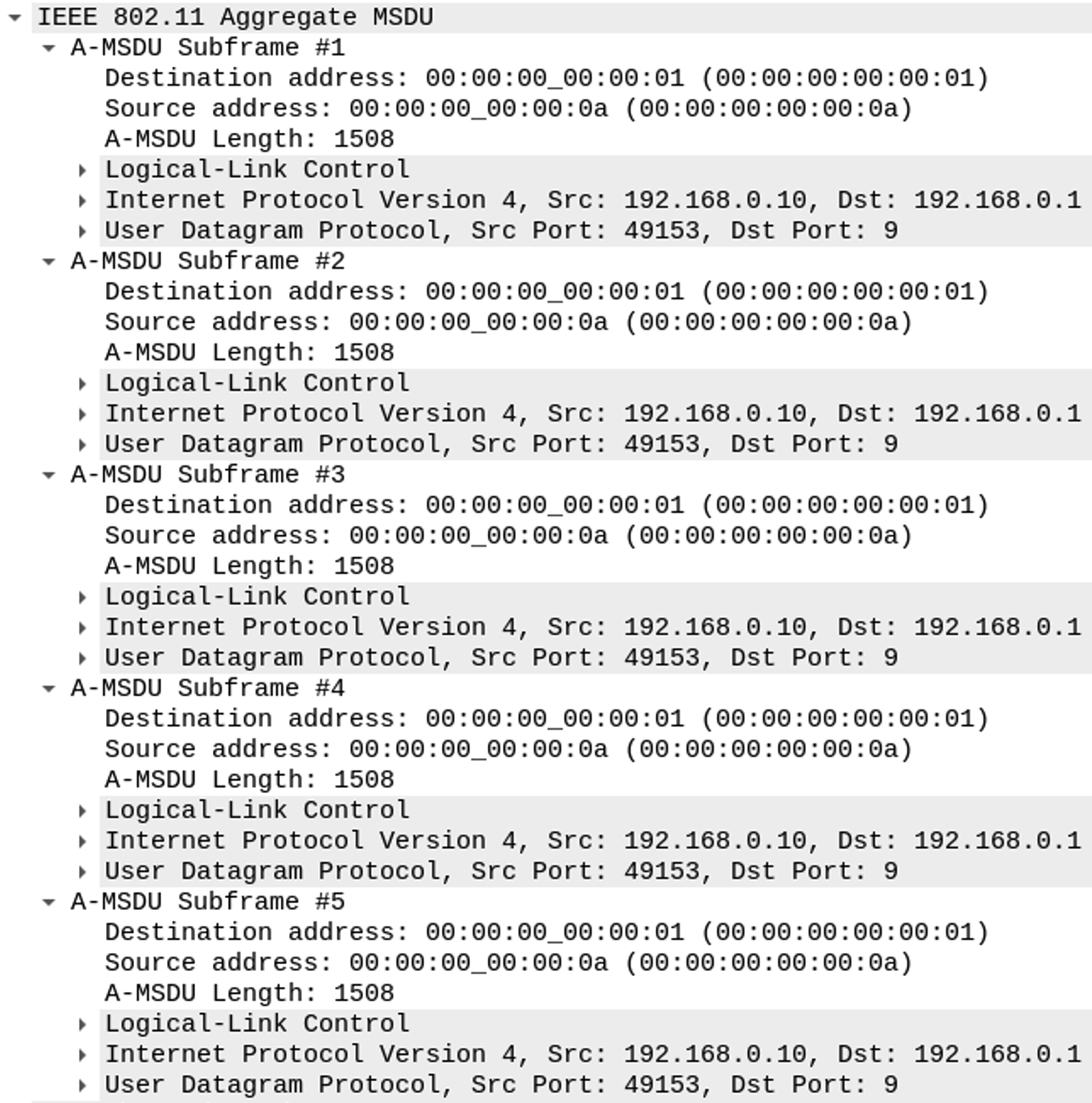
A-MSDU サブフレームごとに DA・SA・A-MSDU Length の 3 つのフィールドがある。
このフレームの RA は 00:00:00:00:00:01 で TA は 00:00:00:00:00:0a なので、
5 つとも DA = RA かつ SA = TA になってる。
Max Length
VHT だと、最大 A-MSDU サイズは直接的には決められてなくて、MPDU サイズによって間接的に制限される。 (IEEE Std 802.11-2020 - p.786)
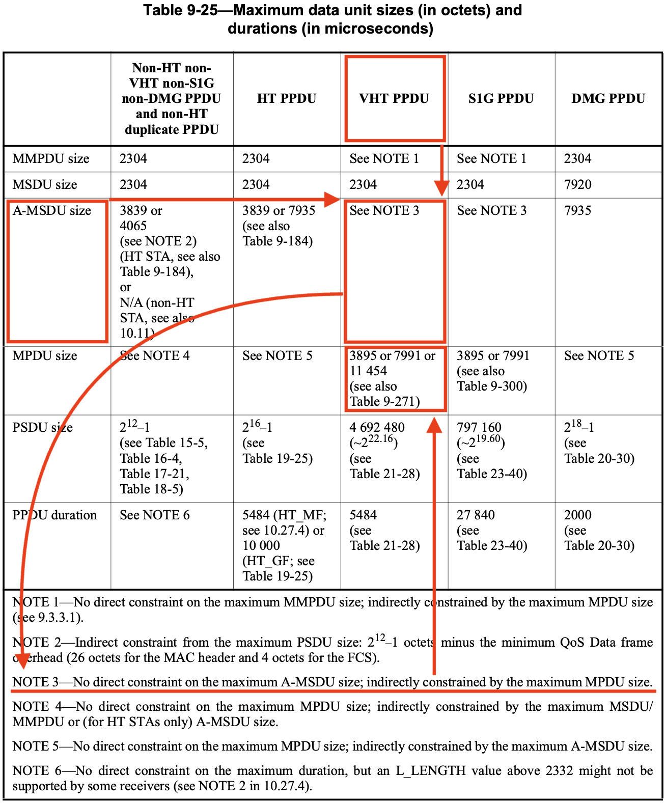
MPDU サイズは Table 9-271 で決められてる。(IEEE Std 802.11-2020 - p.1277)
| Subfield | Definition | Encoding |
|---|---|---|
| Maximum MPDU Length | Indicates the maximum MPDU length that the STA is capable of receiving (see 10.11). | Set to 0 for 3895 octets. Set to 1 for 7991 octets. Set to 2 for 11 454 octets. The value 3 is reserved. |
VHT Capability Information フィールド
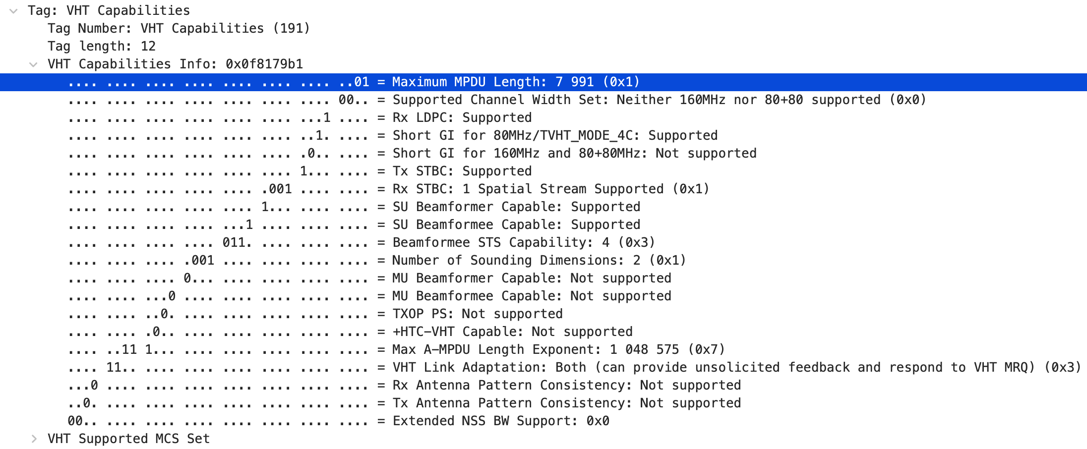
ノーマル Ack ポリシーの QoS Data フレームの中に A-MSDU が含められてた場合、 VHT STA は A-MSDU を Single MPDU として受信できなきゃいけない。
IEEE Std 802.11-2020, p.1716
A STA shall support the reception of an A-MSDU, where the A-MSDU is carried in a QoS Data frame with Normal Ack ack policy in the following cases:
— By an HT STA when the A-MSDU is not aggregated within an A-MPDU
— By a VHT STA when the A-MSDU is sent as an S-MPDU
Block Ack の合意のもとだと、QoS Data フレームの中の A-MSDU の扱いは、それぞれの合意によって決まる。 受信者が A-MSDU を使えるってことを示してなかったら、STA は A-MSDU を送信してはいけない。
IEEE Std 802.11-2020, p.1716
The use of an A-MSDU carried in a QoS Data frame under a block ack agreement is determined for each block ack agreement. A STA shall not transmit an A-MSDU within a QoS Data frame under a block ack agreement unless the recipient indicates support for A-MSDU by setting the A-MSDU Supported field to 1 in its BlockAck Parameter Set field of the ADDBA Response frame.
受信者が送信してきた HT Capabilities element の中の Max A-MSDU Length を超えた長さの A-MSDU を 送信してはいけない。
IEEE Std 802.11-2020, p.1716
A STA shall not transmit an A-MSDU to a STA if the A-MSDU length exceeds the value indicated by the Maximum A-MSDU Length field of the HT Capabilities element received from the recipient STA.
VHT Capabilities element で Max MPDU Length を 7991 か 11454 にセットしてる VHT STA は、 HT Capabilities element では Max A-MSDU Length を 7935 にセットしないといけない。
IEEE Std 802.11-2020, p.1716
A VHT STA that sets the Maximum MPDU Length in the VHT Capabilities element to indicate 7991 octets or 11454 octets shall set the Maximum A-MSDU Length in the HT Capabilities element to indicate 7935 octets.
HT Capabilities Info フィールド
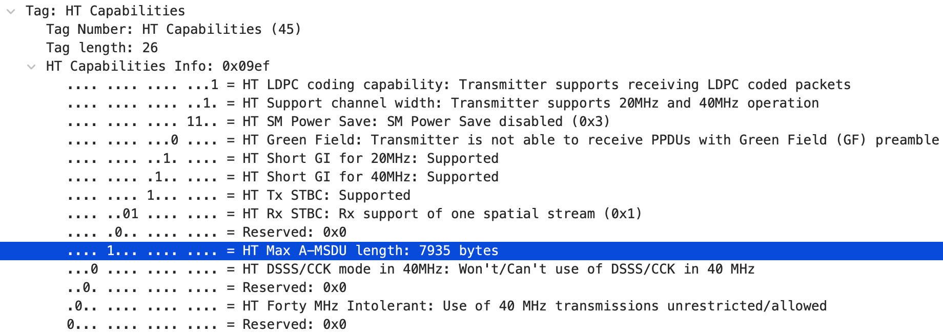
受信側 STA の Max MPDU サイズによって、VHT PPDU 内の A-MSDU の長さは制限される。
IEEE Std 802.11-2020, p.1716
The length of an A-MSDU transmitted in a VHT PPDU is limited by the maximum MPDU size supported by the recipient STA (see 10.12.5).
VHT STA は、受信側 STA から送信された Extended Capabilities element にある Max Number Of MSDUs の 値を超えた数の MSDU を含む A-MSDU を送信してはいけない。
IEEE Std 802.11-2020, p.1716
A VHT STA shall not transmit an A-MSDU that includes a number of MSDUs greater than the value indicated by the Max Number Of MSDUs In A-MSDU field in any Extended Capabilities element sent by the recipient STA.
A-MPDU
A-MPDU (Aggregate MAC Protocol Data Unit) は、複数の MPDU を結合して 1 つの PPDU に含めることでフレーム送信のオーバーヘッドを減らす。
MPDU を結合するには、すべての MPDU が下の 2 つを満たしてないといけない。
- 同一の AC
- 同一の RA
A-MPDU では MPDU ごとに MAC ヘッダーと FCS が追加されるので、オーバーヘッドの削減効果は A-MSDU より小さい。そのかわり、FCS エラーが発生しても該当の MPDU だけが再送される。 ACK として必要になるのは BlockAck フレーム。
下の画像は、ns-3 のシミュレーション(BE_MaxAmpduSize = 1048575)で取得したパケットキャプチャ。
16 個の MPDU が 1 つの A-MPDU として送信されて、それに対する BlockAck フレームが 1 つだけ
返ってきてる。
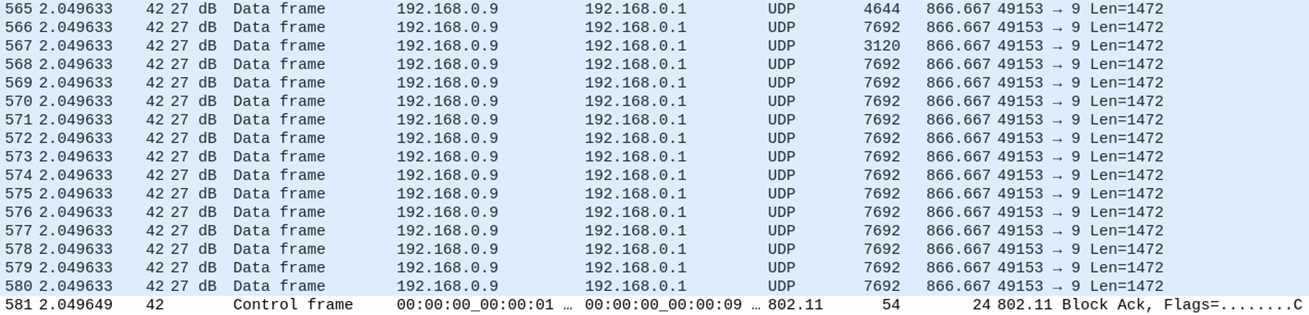
A-MPDU は受信側で分解されてから Wireshark に渡されるので、A-MPDU 全体が 1 つのフレームとして 表示されることはなくて、MPDU ごとに独立したフレームとして表示される。 MPDU Delimiter や EOF Padding もキャプチャには残らない。 同じ A-MPDU に属していたことは、Radiotap ヘッダーの A-MPDU status でわかる。
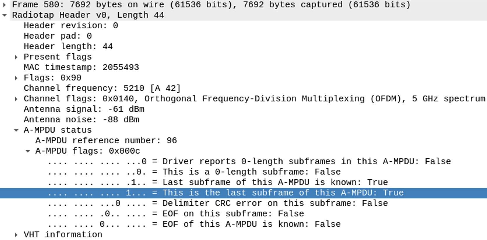
A-MPDU reference number が同じ値(この画像だと 96)の MPDU が、1 つの A-MPDU として送信された MPDU 。最後の MPDU だけ "This is the last subframe of this A-MPDU" が True になってて、 上の画像の 565〜579 番目のフレームは False 、580 番目のフレームだけが True になってる。
ちなみに、A-MPDU の送信が終わってから BlockAck フレームが送信されるまでの時間差は 2.049649 − 2.049633 = 16μs で、SIFS ちょうどの値になってる。
Format
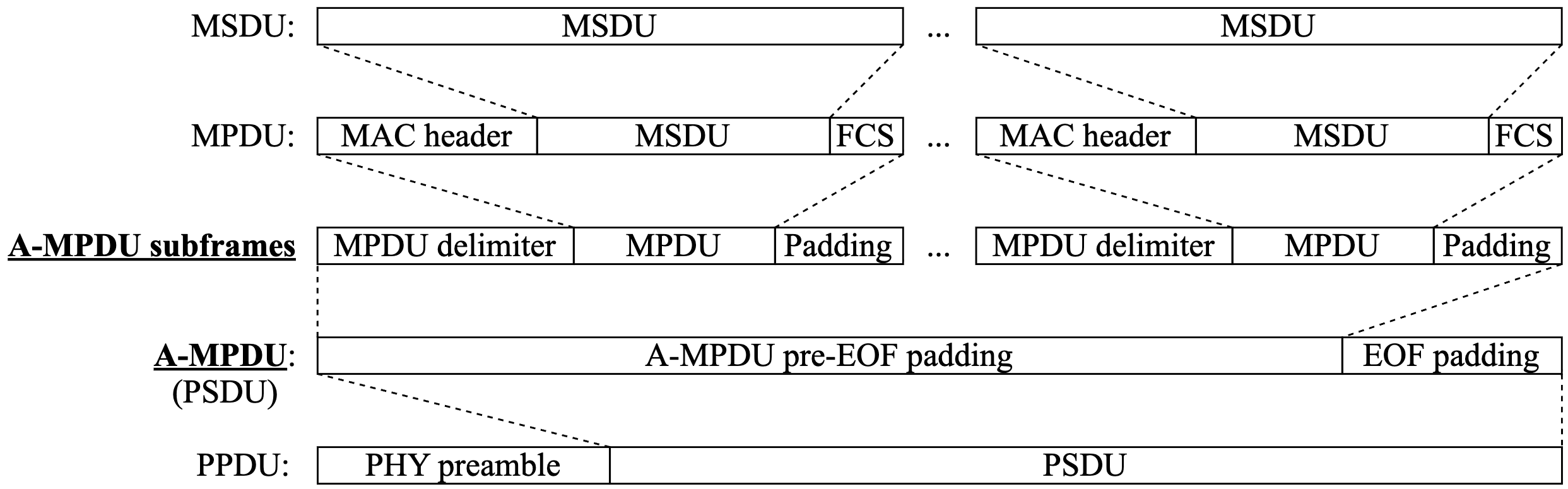
下図は、IEEE Std 802.11-2020 の Figure 9-971〜974 で定義されてるフォーマットを合体させたもの。
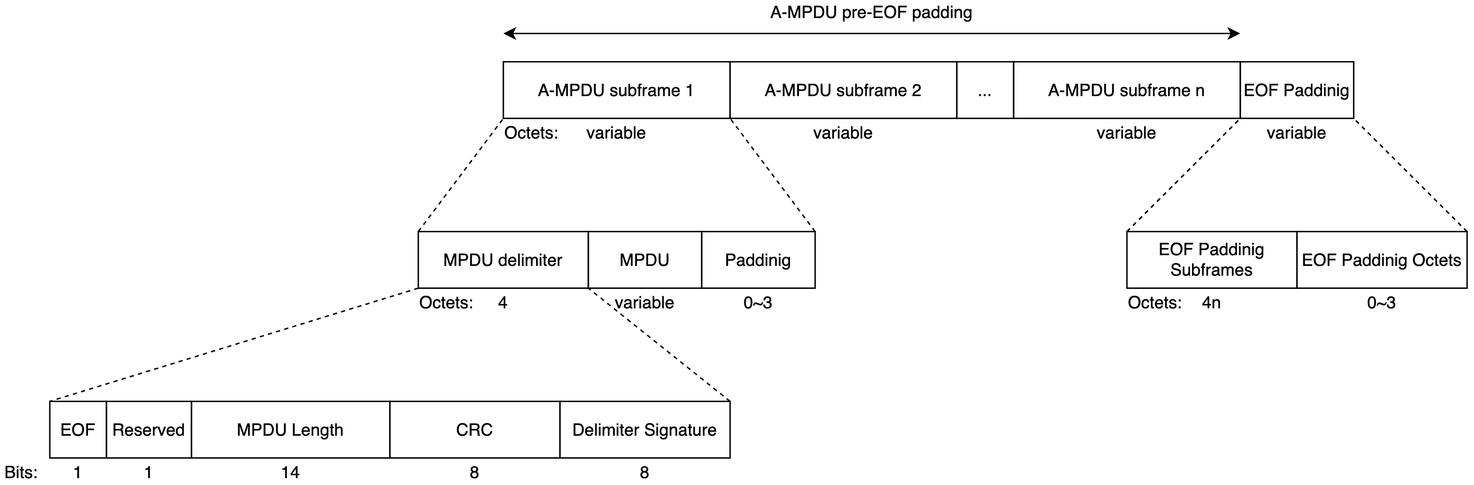
A-MPDU subframe フィールド内にある Padding サブフィールドは、A-MPDU subframe を "4 の倍数" バイトにするためにある。
IEEE Std 802.11-2020, p.1611
Each nonfinal A-MPDU subframe in an A-MPDU has padding octets appended to make the subframe a multiple of 4 octets in length. The content of these octets is unspecified.
MPDU Delimiter サブフィールドは、A-MPDU 内で MPDU がどこに位置するかを示すためにある。復元できるように。
IEEE Std 802.11-2020, p.1614
The purpose of the MPDU delimiter is to locate the MPDUs within the A-MPDU so that the structure of the A-MPDU can usually be recovered when one or more MPDU delimiters are received with errors.
EOF Padding Subframes サブフィールドは、MPDU が空っぽで MPDU Delimiter 内の EOF フィールドが "1" の A-MPDU subframe と同じ。
IEEE Std 802.11-2020, p.1612
The EOF Padding Subframes subfield contains zero or more EOF padding subframes. An EOF padding subframe is an A-MPDU subframe with 0 in the MPDU Length field and 1 in the EOF field.
EOF Padding フィールドが存在する目的は、PHY 層に渡すときに PSDU_LENGTH に適合させるためっぽい。
IEEE Std 802.11-2020, p.1722
Padding is then added for each user such that the resulting A-MPDU contains exactly PSDU_LENGTH octets for that user as follows:
— First, while A-MPDU_Length[n]<PSDU_LENGTH[n] and A-MPDU_Length[n] mod 4 ≠ 0, add an octet to the final A-MPDU subframe's Padding subfield and increment A-PDU_Length[n] by 1.
— Then, while A-MPDU_Length[n]+4 ≦ PSDU_LENGTH[n], add an EOF padding subframe to the EOF Padding Subframes field and increment A-MPDU_Length[n] by 4.
— Finally, while A-MPDU_Length[n]< PSDU_LENGTH[n], add an octet to the EOF Padding Octets subfield and increment A-MPDU_Length[n] by 1.
Max Length
VHT PPDU の A-MPDU の最大値は 1,048,575 bytes、HT PPDU の A-MPDU の最大値は 65,535 bytes。
IEEE Std 802.11-2020, p.1612
The maximum length of an A-MPDU in an HT PPDU is 65 535 octets. The maximum length of an A-MPDU pre-EOF padding in a VHT PPDU is 1 048 575 octets.
VHT Capability Information フィールドでは、指数の値で示される。(IEEE Std 802.11-2020 - p.1279)
| Subfield | Definition | Encoding |
|---|---|---|
| Maximum A-MPDU Length Exponent | Indicates the maximum length of an A-MPDU pre-EOF padding that the STA can receive. | The length defined by this field is equal to 2(13+Maximum A-MPDU Length Exponent)-1 octets. |
VHT Capability Information フィールド
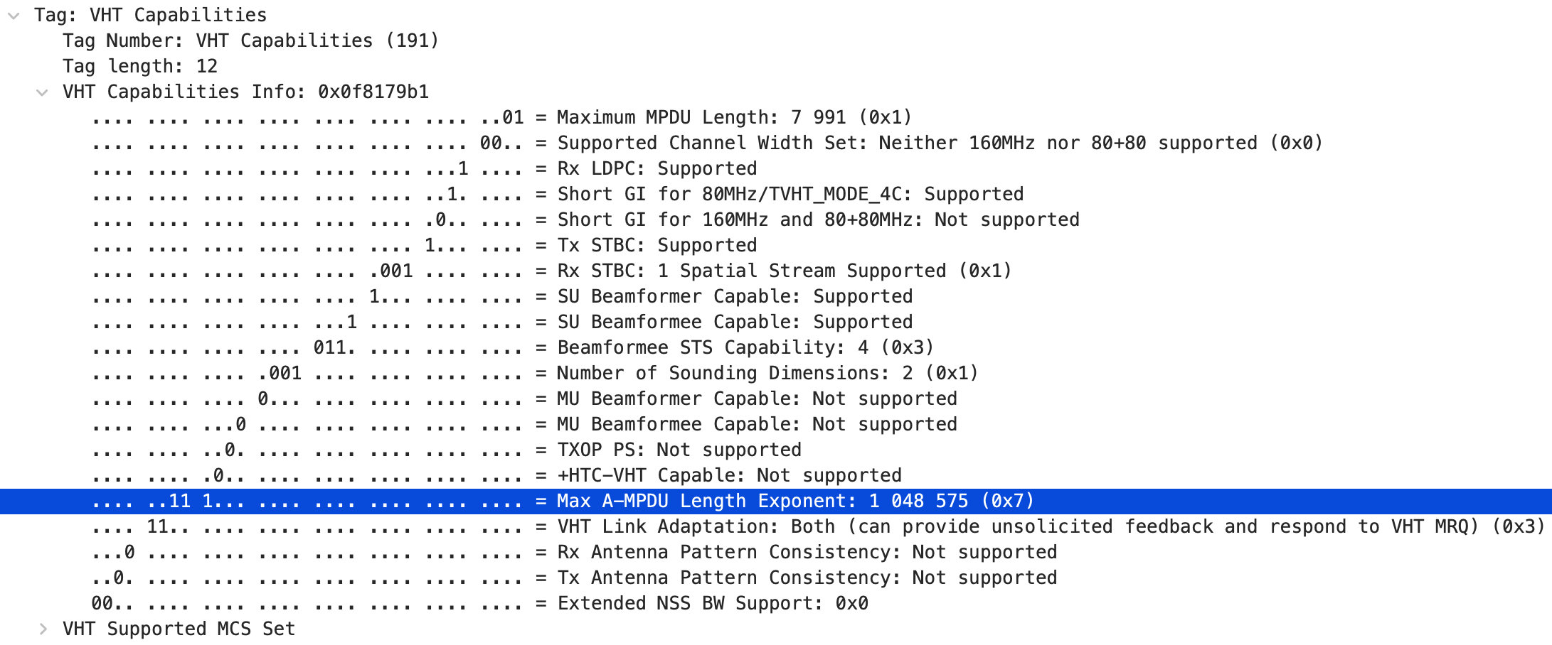
STA は A-MPDU の最大値を HT / VHT Capabilities element で示す。
IEEE Std 802.11-2020, p.1718
A STA indicates in the Maximum A-MPDU Length Exponent field in its HT Capabilities element the maximum A-MPDU length that it can receive in an HT PPDU. A STA indicates in the Maximum A-MPDU Length Exponent field in its VHT Capabilities element the maximum length of the A-MPDU pre-EOF padding that it can receive in a VHT PPDU.
VHT STA が A-MPDU の最大値として 0〜3 の値を設定したいときは、VHT Capabilities element でも HT Capabilities element でも同じ値にしなきゃいけない。3 より大きい値を設定したいときは、 VHT Capabilities element ではその値にして、HT Capabilities element では 3 にしなきゃいけない。
IEEE Std 802.11-2020, p.1719
A VHT STA that sets the Maximum A-MPDU Length Exponent field in its VHT Capabilities element to a value in the range 0 to 3 shall set the Maximum A-MPDU Length Exponent in its HT Capabilities to the same value. A VHT STA that sets the Maximum A-MPDU Length Exponent field in the VHT Capabilities element to a value larger than 3 shall set the Maximum A-MPDU Length Exponent in its HT Capabilities element to 3.
STA は、HT Capabilities element と VHT Capabilities element の Maximum A-MPDU Length Exponent フィールドを使って、自分宛てに送信してもいい A-MPDU pre-EOF padding の最大長を アソシエーションのときに確定させる。
IEEE Std 802.11-2020, p.1719
Using the Maximum A-MPDU Length Exponent fields in the HT Capabilities and VHT Capabilities elements, the STA establishes at association the maximum length of an A-MPDU pre-EOF padding that can be sent to it.
VHT STA は、VHT Capabilities element で設定した最大値の A-MPDU を受信できなきゃいけない。
IEEE Std 802.11-2020, p.1719
A VHT STA shall be capable of receiving A-MPDUs where the A-MPDU pre-EOF padding length is up to the value indicated by the Maximum A-MPDU Length Exponent field in its VHT Capabilities element.
STA は、受信者の HT / VHT Capabilities element で設定された最大値を超える A-MPDU を送信してはいけない。
IEEE Std 802.11-2020, p.1719
A STA shall not transmit an A-MPDU in an HT PPDU that is longer than the value indicated by the Maximum A-MPDU Length Exponent field in the HT Capabilities element received from the intended receiver. MPDUs in an A-MPDU carried in an HT PPDU shall be limited to a maximum length of 4095 octets. A STA shall not transmit an A-MPDU in a VHT PPDU where the A-MPDU pre-EOF padding length is longer than the value indicated by the Maximum A-MPDU Length Exponent field in the VHT Capabilities element received from the intended receiver.
Block Ack
複数のフレームにまとめてAckを送信できるのが Block Ack 。TXOP の間に送信された複数のフレームや A-MPDU に対する ACK は、BlockAck フレームとしてまとめて送信できる。
CWNA Study Guide, p.392
However, an A-MPDU frame contains multiple MPDUs, each with its own unique MAC header. Each of the individual MPDUs must be acknowledged; this is accomplished by using a Block ACK frame. Block ACKs were first introduced by the 802.11e amendments as a method of acknowledging multiple individual 802.11 frames during a frame burst.
通常の ACK だとフレームごとに SIFS と Ack フレームの送信が必要となるけど、 Block Ack では複数のフレームに対して SIFS と BlockAck フレーム 1 つの送信となる。 なので、EDCA では TXOP によるフレーム送信の効率化だけではなく、Block Ack による ACK の効率化も実現されている。
IEEE Std 802.11-2020, p.1785
The block ack mechanism improves channel efficiency by aggregating several acknowledgments into one frame.
BlockAck フレームの送信前に使われる IFS も、通常の Ack フレームと同じで SIFS 。
IEEE Std 802.11-2020, p.1643
The SIFS shall be used prior to transmission of each of the following frames:
— A PPDU containing a BlockAck frame, NDP BlockAck frame, or BAT frame that is an immediate response to a BlockAckReq frame or an A-MPDU
Block Ack Agreement
frame burst とか A-MPDU で複数の QoS Data フレームを送信して Block Ack を要求する前に、Management フレームの 1 種の Action フレーム(ADDBA Request フレームと ADDBA Response フレーム)で Block Ack に必要なパラメーターを交換することによって、Block Ack Agreement が行われる。 Block Ack メカニズムが初期化された後なら、QoS Data フレームのブロック (BlockAck フレームで返事してっていう複数のフレーム)を送信してもいい。
IEEE Std 802.11-2020, p.1785
The block ack mechanism is initialized by an exchange of ADDBA Request/Response frames except for GLK-GCR block ack. After initialization, blocks of QoS Data frames may be transmitted from the originator to the recipient.
Block Ack に関する Action フレームは、Wireshark で wlan.fixed.category_code == 3 の
ディスプレイフィルターをかけると抽出できる。

Dialog Token が同じ値のものが、1 組の ADDBA Request フレームと ADDBA Response フレーム。 Block Ack Agreement は方向ごとに結ばれるので、STA から Request を送る場合と AP から Request を 送る場合の両方がある。上の画像だと、Dialog Token が 1 のものだけ AP 側から Request を送ってる。 Buffer Size を変更するために、もう一度 Block Ack Agreement をすることもある。
ADDBA Request
ADDBA Request フレームのうち、Block Ack に関係するのは Order 1〜6 のフィールド。 (IEEE Std 802.11-2020 - Table 9-360—ADDBA Request frame Action field format)
| Order | Information |
|---|---|
| 1 | Category |
| 2 | Block Ack Action |
| 3 | Dialog Token |
| 4 | Block Ack Parameter Set |
| 5 | Block Ack Timeout Value |
| 6 | Block Ack Starting Sequence Control |
| 7 | GCR Group Address element (optional) |
| 8 | Multi-band (optional) |
| 9 | TCLAS (optional) |
| 10 | ADDBA Extension (optional) |
実際のフレーム
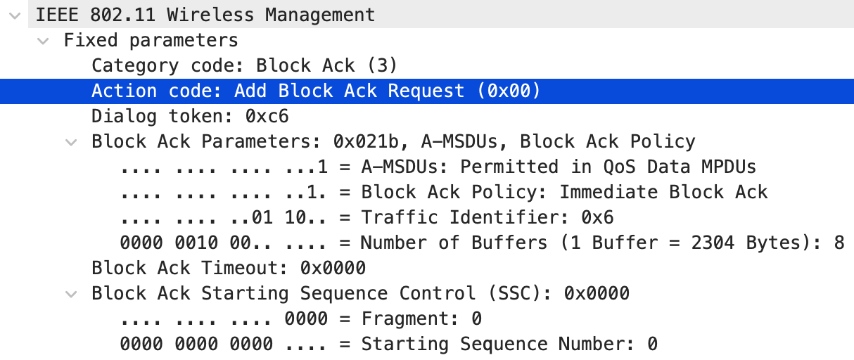
-
Category: Block Ackなら"3"
IEEE Std 802.11-2020, p.880
The Category field is set to one of the nonreserved values shown in the Code column of Table9-51.
(IEEE Std 802.11-2020 - Table 9-51—Category values ※一部省略あり)
Code Meaning See subclause Robust Group addressed privacy 0 Spectrum Management 9.6.2 Yes No 1 QoS 9.6.3 Yes No 2 Reserved 3 Block Ack 9.6.4 Yes No -
Block Ack Action: ADDBA Requestなら"0"
(IEEE Std 802.11-2020 - Table 9-359—Block Ack Action field values)
Block Ack Action field values Meaning 0 ADDBA Request 1 ADDBA Response -
Dialog Token: 同じActionに対するRequest/ResponseのDialog Tokenは同じ値を使う
IEEE Std 802.11-2020, p.881
-
The Dialog Token field is used for matching action responses with action requests when there are multiple concurrent action requests.
-
The length of the Dialog Token field is 1 octet.
-
-
Block Ack Parameter Set
(IEEE Std 802.11-2020 - Figure 9-96—Block Ack Parameter Set field format)
サブフィールド ビット 長さ (bits) A-MSDU Supported B0 1 Block Ack Policy B1 1 TID B2〜B5 4 Buffer Size B6〜B15 10 -
A-MSDU Supported: この Block Ack Agreement のもとで A-MSDU 入りの QoS Data フレームを送ってもいいかどうか。
IEEE Std 802.11-2020, p.881
The A-MSDU Supported subfield is set to 1 by a STA to indicate that it supports an A-MSDU carried in a QoS Data frame sent under this block ack agreement. It is set to 0 otherwise.
-
Block Ack Policy: ほぼ確実に"1"
IEEE Std 802.11-2020, p.881
The Block Ack Policy subfield is set to 1 for immediate or HT-immediate block ack
immediate block ack の他には、delayed block ack っていうのがあるらしいけど、"Deprecated"に なってる; Block Ack Policy は"1"以外あり得ないのでは。
IEEE Std 802.11-2020, p.3568
dot11DelayedBlockAckOptionImplemented OBJECT-TYPE SYNTAX TruthValue MAX-ACCESS read-only STATUS Deprecated DESCRIPTION "Deprecated as the related feature has been removed from IEEE Std 802.11. This is a capability variable. Its value is determined by device capabilities. This attribute, when true, indicates that the station implementation is capable of supporting delayed block ack. The capability is disabled, otherwise." ::= { dot11StationConfigEntry 32 } -
TID
IEEE Std 802.11-2020, p.881
The TID subfield contains the TC or TS for which the BlockAck frame is being requested.
-
Buffer Size: Wiresharkの表示も合わせてみると、BlockAck フレームを返すまでに、2304bytes x BufferSizeの分だけフレームを保持できるってことみたい
IEEE Std 802.11-2020, p.881
The Buffer Size subfield indicates the number of buffers available for this particular TID.
IEEE Std 802.11-2020, p.882
When the A-MSDU Supported field is equal to 1 as indicated by the STA, each buffer is capable of holding a number of octets equal to the maximum size of an A-MSDU that is supported by the STA.
ADDBA Requestの時に"0"で送ると、Responseで値を決めてくれって相手に言ってるみたいな。
IEEE Std 802.11-2020, p.882
In an ADDBA Request frame, the Buffer Size subfield provides guidance for the frame receiver to decide its reordering buffer size. If the Buffer Size subfield is equal to 0, it implies that the originator of the block ack has no information to specify its value.
-
-
Block Ack Timeout Value: このBlock Ack Agreementのタイムアウトを設定、"0"ならタイムアウトを無効にする
IEEE Std 802.11-2020, p.882
-
The Block Ack Timeout Value field is used in the ADDBA Request and Response frames to indicate the timeout value for a block ack agreement.
-
The field is set to 0 to disable the timeout.
-
-
Block Ack Starting Sequence Control: Fragment Numberサブフィールドは"0"(固定)、Starting Sequence NumberサブフィールドでBlockAck フレームを返して欲しいMSDUの番号を伝える
IEEE Std 802.11-2020, p.800
The Starting Sequence Number subfield of the Block Ack Starting Sequence Control subfield contains the sequence number of the first MSDU or A-MSDU for which this BlockAckReq frame is sent. The Fragment Number subfield of the Block Ack Starting Sequence Control subfield is set to 0.
ADDBA Response
ADDBA Response フレームのうち、Block Ack に関係するのは Order 1〜6 のフィールド。 (IEEE Std 802.11-2020 - Table 9-361—ADDBA Response frame Action field format)
| Order | Information |
|---|---|
| 1 | Category |
| 2 | Block Ack Action |
| 3 | Dialog Token |
| 4 | Status Code |
| 5 | Block Ack Parameter Set |
| 6 | Block Ack Timeout Value |
| 7 | GCR Group Address element (optional) |
| 8 | Multi-band (optional) |
| 9 | TCLAS (optional) |
| 10 | ADDBA Extension (optional) |
| 11 | Originator Preferred MCS (optional) |
実際のフレーム
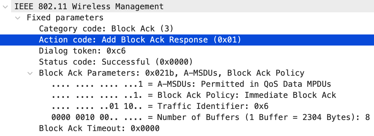
ADDBA Request フレームと比べると、Block Ack Starting Sequence Control が無くなって、 Status Code が増える。
-
Category: Block Ackなら"3"
- 上記と同じ
-
Block Ack Action: ADDBA Responseなら"1"
- 上記と同じ
-
Dialog Token: 同じActionに対するRequest/ResponseのDialog Tokenは同じ値を使う
- 上記と同じ
-
Status Code: successなら"0"
IEEE Std 802.11-2020, p.874
-
The Status Code field is used in a response Management frame to indicate the success or failure of a requested operation.
-
If an operation is successful, then the status code is set to SUCCESS (0).
-
-
Block Ack Parameter Set
IEEE Std 802.11-2020, p.882
In an ADDBA Response frame, when the Status Code field is equal to SUCCESS, the Buffer Size subfield is set to at least 1.
-
Block Ack Timeout Value
- 上記と同じ
BlockAck frame
Block Ack Agreement が確立した後は、複数の QoS Data フレームに対する ACK が BlockAck フレームで 返される。BlockAck フレームは Control フレームの 1 種。
(IEEE Std 802.11-2020 - Figure 9-41—BlockAck frame format)
| Field | Frame Control | Duration | RA | TA | BA Control | BA Information | FCS |
|---|---|---|---|---|---|---|---|
| Octets | 2 | 2 | 6 | 6 | 2 | variable | 4 |
RA は BlockAck フレームを要求した recipient STA のアドレスで、TA は BlockAck フレームを送信する STA のアドレス。
IEEE Std 802.11-2020, p.802
-
The RA field of the BlockAck frame is the address of the recipient STA that requested the BlockAck frame.
-
The TA field value is the address of the STA transmitting the BlockAck frame.
実際のフレーム
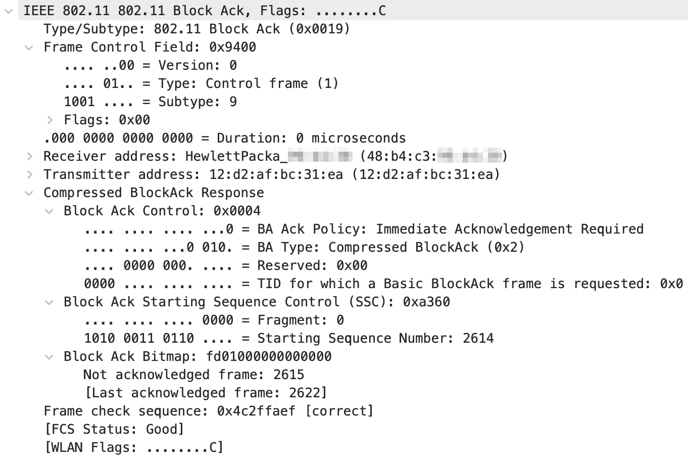
-
BA Control: Compressed BlockAck フレームの TID_INFO サブフィールドには、この BlockAck フレームを送信する対象の TID が入る
(IEEE Std 802.11-2020 - Figure 9-42—BA Control field format)
サブフィールド Reserved Multi-TID Compressed Bitmap GCR Mode Reserved TID_INFO ビット B0 B1 B2 B3〜B4 B5〜B11 B12〜B15 長さ (bits) 1 1 1 2 7 4 IEEE Std 802.11-2020, p.803
The TID_INFO subfield of the BA Control field of the Compressed BlockAck frame contains the TID for which this BlockAck frame is sent.
Wireshark は B1〜B4 をまとめて BA Type として表示する。上の画像の
BA Type: Compressed BlockAck (0x2)は、Multi-TID が 0 で Compressed Bitmap が 1 、GCR Mode が 0 の状態にあたる。TID_INFO はTID for which a Basic BlockAck frame is requestedという名前で表示される -
BA Information: Compressed BlockAck フレームでは、Block Ack Starting Sequence Control サブフィールドと Block Ack Bitmap サブフィールドで構成される
(IEEE Std 802.11-2020 - Figure 9-43—BA Information field format (Compressed BlockAck))
サブフィールド Block Ack Starting Sequence Control Block Ack Bitmap Octets 2 8 IEEE Std 802.11-2020, p.804
The BA Information field of the Compressed BlockAck frame comprises the Block Ack Starting Sequence Control subfield and the Block Ack Bitmap subfield, as shown in Figure 9-43. The Block Ack Starting Sequence Control subfield is shown in Figure 9-37. The Starting Sequence Number subfield of the Block Ack Starting Sequence Control subfield contains the sequence number of the first MSDU or A-MSDU for which this BlockAck frame is sent. This subfield is defined in 10.25.6.5. The Fragment Number subfield of the Block Ack Starting Sequence Control subfield is set to 0.
-
Block Ack Bitmap: ビットが 1 なら、対応する MSDU か A-MSDU を受信できたということ。最大 64 個分の受信状況を示せて、先頭のビットが Starting Sequence Number に対応する
IEEE Std 802.11-2020, p.804
The Block Ack Bitmap subfield of the BA Information field of the Compressed BlockAck frame is used to indicate the received status of up to 64 entries, where each entry represents an MSDU or an A-MSDU. Each bit that is equal to 1 in the compressed Block Ack Bitmap field acknowledges the reception of a single MSDU or A-MSDU in the order of sequence number, with the first bit of the Block Ack Bitmap field corresponding to the MSDU or A-MSDU with the sequence number that matches the Starting Sequence Number subfield of the Block Ack Starting Sequence Control subfield.
上の画像だと、SSC の Starting Sequence Number が 2614 で、Block Ack Bitmap が
fd 01 00 00 00 00 00 00 。先頭のオクテット 0xfd は 1111 1101 なので、bit 1 だけが 0 になってる。
bit 0 が Sequence Number 2614 に対応するので、2615 だけ受信できなかったことになる。
2 オクテット目の 0x01 は bit 8 で、Sequence Number 2622 に対応する。
Wireshark も Not acknowledged frame: 2615 と [Last acknowledged frame: 2622] を出してくれる。
なのでこの BlockAck フレーム 1 つで、2614 から 2622 までの 9 個の MPDU の受信状況を返してる。 再送が必要なのは 2615 だけで、他の 8 個は再送しなくていい。 A-MPDU は、FCS エラーが発生した MPDU を Starting Sequence Number と Block Ack Bitmap で特定してる。
References
- IEEE 802.11 Working Group (2020), IEEE Standard for Information Technology — Telecommunications and Information Exchange between Systems Local and Metropolitan Area Networks — Specific Requirements Part 11: Wireless LAN Medium Access Control (MAC) and Physical Layer (PHY) Specifications
- Wi-Fi Alliance, “Wi-Fi Multimedia Technical Specification Version 1.2.0”
- David D. Coleman & David A. Westcott (2021), CWNA: Certified Wireless Network Administrator Study Guide Exam CWNA-108, 6th ed, John Wiley & Sons
- David Westcott, et al. (2011), CWAP: Certified Wireless Analysis Professional Official Study Guide: Exam PW0-270, Wiley
- Tom Carpenter, et al. (2021), Certified Wireless Analysis Professional (CWAP) Official Study Guide (CWAP-404), CertiTrek
- Wi-Fi Alliance (2009), “Wi-Fi CERTIFIED n: Longer-Range, Faster-Throughput, Multimedia-Grade Wi-Fi Networks”